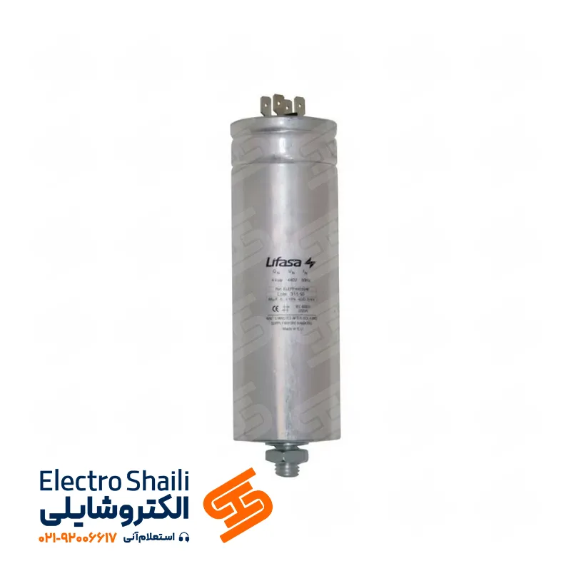
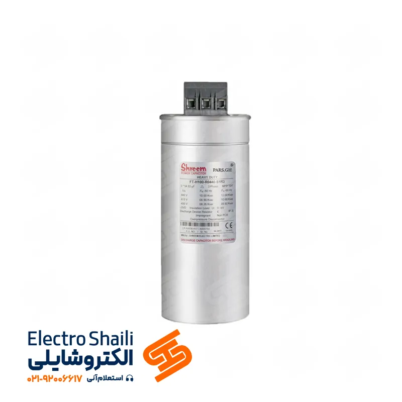
What is a Harmonic Filter Capacitor Bank?
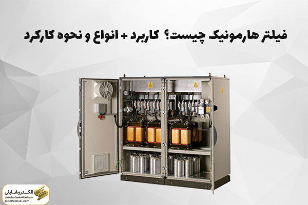
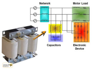
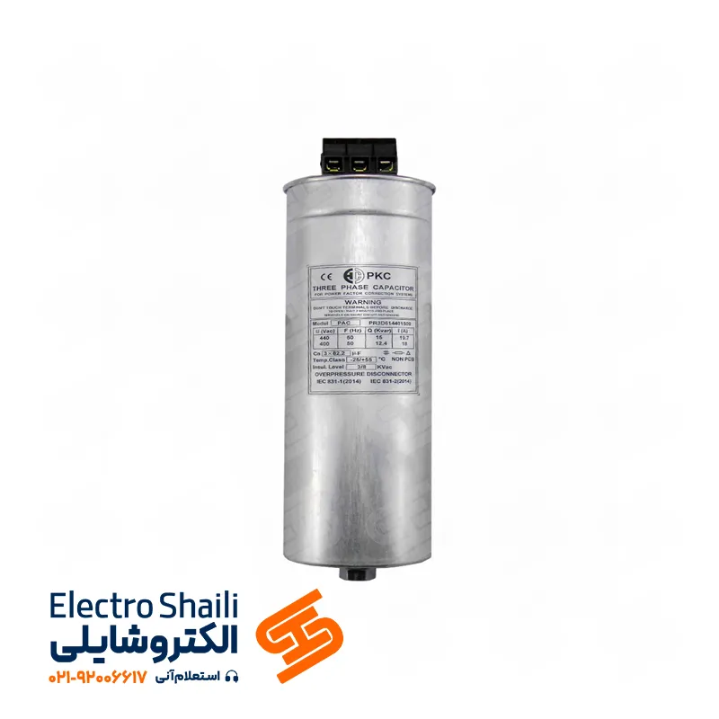
A harmonic filter capacitor bank is an electronic device designed to reduce harmful harmonics and electrical noise in electrical systems. This filter utilizes capacitors as its main elements to absorb harmonic currents and eliminate them from the circuit.
The primary application of a harmonic filter capacitor bank is to address the harmonics generated by non-linear loads. Loads consisting of diodes, power electronics, or other non-linear electrical devices may produce undesirable harmonics, leading to increased noise and disturbances in the power network. The harmonic filter effectively absorbs these harmonics and balances the electric current, significantly improving the power supply quality and preserving the health of electrical equipment.
The capacitor bank in this filter acts as an energy storage device, actively absorbing and eliminating harmonic currents from the network. This direct reduction of harmonic currents enhances the stability and optimization of the electrical system’s performance.
The use of harmonic filter capacitor banks in industrial, commercial, or even residential energy supply systems can result in a considerable improvement in the performance and efficiency of electrical and electronic equipment. These advanced tools serve as an efficient solution to reduce harmonics and enhance power supply quality in electrical networks.
What is a Capacitor Harmonic Filter?
A capacitor harmonic filter acts as a guardian against various harmonics. This filter works by controlling harmonics and preventing their entry into the capacitor. Compensation of reactive power, as a cost optimization tool, and rapid return of capital are considered benefits of this filter. In recent years, with the use of innovative materials and advanced manufacturing technologies, capacitors with very low losses in small volumes have been developed.
The development and production of advanced microprocessor-based capacitor contactors and regulators, ensuring optimal and efficient capacitor bank behavior against load changes, have made capacitor banks entirely reliable.
The importance of consultants and consumers’ awareness of the complex challenges in the field of capacitor banks
Facing the increasing harmonic fluctuations in weak and medium voltage networks, the process of designing capacitor banks has become a complex and challenging task. Various devices such as structures, electronic motor controllers, frequency converters, and electronic loads require capacitors for reactive power balance. This is while consumers also act as harmonic generators.
In the case of resonance frequency alignment between the transformer and the capacitor, serious hazards arise. Therefore, it is highly recommended that experienced individuals in proper planning serve as consultants to address the design appropriately and prevent potential issues and costs.
Understanding the Harmonic Phenomenon in Weak Power Networks
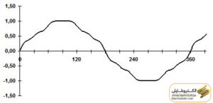
Harmonics are an electrical phenomenon that intensifies with the use of non-sinusoidal consumers in weak power networks. Non-sinusoidal currents passing through the network cause voltage drop from the network’s impedance, resulting in distortions in the sinusoidal voltage of the network.
These distortions can be explained using the Fourier series concept, where all waves (Fourier series terms) with a frequency equal to a multiple of the base frequency (network frequency) are well known. This phenomenon leads to voltage drop and disturbances in the power system, which is of great importance in optimizing power networks.
The question that always comes to the minds of those working in the field of electricity is, what percentage of the harmonic domain exists?
Studies show that 5% of the fifth harmonic domain, 4% of the seventh harmonic domain, and 2.5% of the eleventh harmonic domain constitute the harmonics. This information is essential not only for industrial loads but also for household purposes.
In fact, non-linear loads are recognized as the main generators of harmonics in the power network. These harmonics are usually present at the third, fifth, seventh, eleventh, and thirteenth orders. This fact underscores the importance of examining and optimally managing these harmonics in electrical systems.
Origin of Harmonics: A Quest in the World of Technology
What role do harmonics play in the electrical system? This important question arises in industrial environments, especially when variable-speed drives of induction motors are in operation.
Aside from industrial settings, harmonics are present in all residential and commercial buildings. Televisions, computers, and even energy-saving light bulbs contribute to the generation of these harmonics. This complex exploration in the realms of technology and electricity emphasizes the importance of examining and appropriately managing harmonics in all aspects of life.
Effect of Capacitors on Harmonics: A Comprehensive Guide
Before installing capacitors, the level and types of harmonics depend on the number of non-linear loads in the network. As a detailed example, installing a 6-pulse thyristor rectifier with a power that constitutes 50% of the transformer power will create the fifth harmonic with a range of 4% and the seventh harmonic with a range of 3% in the network.
When a large number of thyristor rectifiers are installed, the impact of harmonics from the rectifiers minimizes due to the phase difference of their currents. For instance, if a thyristor rectifier with a total power of 25% of the transformer’s rated power is installed, the harmonics with the main wave ranges will be as follows:
– Fifth harmonic with a range of 1% to 1.51%
– Seventh harmonic with a range of 0.7% to 1%
The effect of a capacitor bank without a filter, measured close to the resonance frequency, introduces added resonance voltage and current. This information assists engineers and decision-makers in optimizing electrical systems.
Designing a Capacitor Bank for a Harmonic Network
Importance of Information in Capacitor Bank Design: A Comprehensive Guide
In the capacitor bank design phase, the precise combination of information obtained from measuring voltage and current harmonics over several days without capacitors significantly determines the optimal path for design. This information includes calculating the resonance frequency theoretically and the maximum amplitude of measured harmonic ranges, which greatly influences the effectiveness coefficient obtained from the network analyzer.
For example, in a weak power network with a 1000 kW ampere transformer, when installing a complete capacitor bank (400 kW) in the circuit, the fifth harmonic will triple, and the seventh harmonic will quadruple.
Additionally, the presence of harmonics at various percentages in medium voltage networks requires careful examination. Here are a few examples of harmonics at different order frequencies. In situations where the harmonic voltage range exceeds standard values, using a capacitor bank with a coil is recommended, especially if the fifth harmonic has more than 2% or the seventh harmonic and above exceeds 1%.
In selecting a capacitor bank, important considerations include the bank being equipped with a filter and avoiding the simultaneous use of capacitor banks with and without filters in a common weak power network. Also, capacitor banks equipped with filters with different resonance frequencies can be installed in parallel to reduce the likelihood of the bank being subjected to an additional load with a higher resonance frequency. These guidelines assist engineers and decision-makers in choosing and optimizing capacitor banks.
Types of Harmonic Filters in Capacitor Banks: A Complete Guide
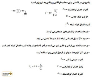
When the resonance frequency matches the frequency of one of the harmonic components, resonance occurs in the network. Under these conditions, the effective voltage of the network experiences slight variations over time, while the effective current of the capacitor bank sharply increases.
To prevent this phenomenon, which may damage capacitors and equipment, the use of harmonic filters is essential. Filters are divided into two main categories: active and passive, each with its own characteristics and applications.
Passive filters are further divided into Tuned and Detuned categories and are usually used in situations where economic considerations are essential, and there is no need for an active filter. Due to their mode of operation, these filters can minimize the resonance frequency difference in the network.
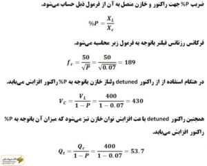
In conditions where the network power factor is low, and there is a need for capacitor switching, Detuned filters are used to prevent resonance, and detuning the resonance frequency helps prevent the capacitor frequency from aligning with the dominant harmonic frequency of the network.
Depending on the dominant harmonic of the network, we need one of the two filter types, P=14% and P=7%. These filters can remove harmonics from the fifth order and above and the third order and above, and their cost is approximately twice that of the 7% filters.
In situations where the goal is to reduce harmonics at the points of connection of non-linear loads, and there is a need to reduce the current total harmonic distortion (THD) in the network or keep it below a permissible limit, the use of Tuned filters is recommended. These filters are usually accompanied by a Thyristor Switched Reactor (TCR), and in conditions where the load is highly variable, it is advisable for the load to be uniform.
Moreover, active filters, by generating an equal and opposite current to the direction of harmonics, can help improve the network power factor and reduce THD in the current. In general, the simultaneous use of active and Detuned filters in a capacitor bank can correct the power factor of the network, reduce
