Types of Electric Generators
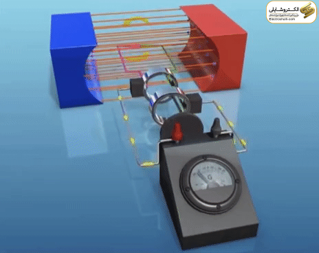
Voltage inside an electric generator is produced by a magnetic flux interacting with a coiled wire. The phenomenon of electromagnetic induction shows that the presence of a coiled wire in a varying magnetic field over time creates an electromotive force (EMF). Changes in the magnetic field occur due to two factors: alternating current or the rotational movement of the coiled wire in the field, inducing electric current in the wire.

There are two methods for creating changes in the magnetic field: first, the magnetic field around a stationary conductor rotates, and second, a conductor within a magnetic field rotates and creates changes in magnetic field lines, inducing electric current in the coiled wire.
Components of a Generator:
1. Engine:
The generator’s engine acts as the main driving force and converts fuel into mechanical energy.
Various types of engines, including reciprocating engines, steam engines, turbine engines, and microturbines, may be used.
The engine’s fuel can be gasoline, diesel, natural gas, propane, biodiesel, water, sewage gas, or hydrogen.
2. Generator:
The power generator is an electricity-producing device that converts the mechanical energy generated by the engine into electrical energy.
The generator’s structure includes a stator and a rotor, creating an electromagnetism flow.
3. Fuel System:
Includes a fuel tank, fuel pump, fuel filter, and injector.
The fuel system is responsible for collecting and transferring fuel from the tank to the engine.
4. Voltage Regulator:
This part of the generator is used to adjust and control the generated voltage.
The voltage regulator is used to regulate and maintain the output voltage.
5. Cooling and Exhaust Systems:
The cooling system prevents excessive heat and regulates the temperature of the generator components.
The exhaust system is used to expel harmful gases produced from fuel consumption.
6. Lubrication System:
This system is responsible for keeping the moving parts of the generator lubricated and injecting oil into the necessary points.
Regular oil changes and monitoring its level are of great importance.
7. Battery Charger:
The battery is used at the beginning of the generator’s operation to initiate the process.
The battery charger is responsible for charging and monitoring the battery level.
8. Control Panel:
The control panel is responsible for the electrical control of the entire generator system.
Control and monitoring of voltage, current, frequency, and other important parameters are part of this section.
9. Main Frame:
The main frame or chassis of the generator’s engine is the main structure where all the above components are installed.
This part can be portable or stationary and accommodates the equipment.
Generator Design
The components of a three-phase AC generator are observed in the figure below.

Difference between Salient Pole and Smooth Pole Rotors
The rotor structure is formed in two types: salient pole and smooth pole. In the salient pole rotor, the poles appear more prominent than the rotor surface and are mainly used in generators with 4 or more poles. On the other hand, in the smooth pole rotor, the poles are of the same height as the rotor surface and are primarily used in synchronous generators and 2 or 4-pole turbo-generators.
Salient pole rotors are used in low-speed hydroelectric generators and multipolar generators. For example, these rotors are used in low-speed machines such as hydroelectric power plants. In contrast, smooth pole rotors are used in high-speed generators. The figure below carefully illustrates the structural differences between the salient pole rotor and the smooth pole rotor (hidden pole) in a generator.
Types of Generators
Generators are generally divided into two categories: AC and DC.
AC Generators
AC generators, or alternators, are devices that convert mechanical power into AC electrical power. This type of generator is designed to produce alternating current with a frequency of 50 or 60 hertz. The structure of an AC generator consists of a coil or loop of wire in a magnetic field generated by an electromagnet.
The two ends of the loop are connected to sliding rings and are in contact with two brushes. These rings provide the circuit with current through the brushes. When the loop rotates, it cuts magnetic lines of force, first in one direction and then in the other.
When the loop is in the vertical position (0 degrees), the coil is parallel to the field, and magnetic lines of force are not cut. At this moment, no voltage is generated from the loop. However, as the coil rotates clockwise, the coil turns cut the magnetic lines of force oppositely, leading to voltage generation.
The direction of induced voltages depends on the direction of coil movement. Induced voltages add up in series, with the sliding ring X acting as positive (+) and the sliding ring Y acting as negative (-). As a result, the potential existing in resistance R causes electric current to flow from Y to X through the resistance.
When the coil is horizontally oriented relative to the magnetic lines of force (90 degrees), the current increases to its maximum. In this position, the coil moves perpendicular to the field, cutting the maximum number of magnetic force lines.
As the coil continues to rotate, induced voltages and currents decrease to zero until the coil returns to the vertical position (180 degrees). In the second half of the rotation, the voltage polarity reverses (270 and 360 degrees). This polarity change, with a 360-degree rotation of the coil, results in the production of an AC sine wave.
DC Generators
DC generators are another type of generator that converts mechanical energy into DC electrical energy. The induced current in the armature windings is initially alternating and is converted to direct current (DC) using a commutator (a segmented cylindrical sliding ring).

The commutator, a segmented cylindrical sliding ring with gaps, is connected to the armature and creates changes in current. In a DC generator, the commutator collects current from the rotating armature and sends it to the load as direct current. In other words, the commutator in a DC generator is responsible for collecting and taking current.
The brushes in a DC generator lift the current from the commutator and transfer it to the circuit. In the structure of a DC generator, the two ends of the wire loop are connected to the commutator. With the rotation of the wire loop in the magnetic field, the slotted commutator comes into motion, and each half of the slotted commutator is in contact with brushes. The brushes establish an external circuit connection with the rotating wire. The induced voltage’s magnitude depends on the angle of the wire’s movement relative to the magnetic lines of flux, as the flux lines cut by the wire depend on the movement angle.
In the second half of the rotation, the brushes switch to the opposite commutator, causing the output voltage polarity not to change. By increasing the number of loops to two or more, the average voltage increases, resulting in smoother ripple.
Equivalent Circuit of DC Generator or Self-Excited Generator
In the equivalent circuit of a self-excited DC generator, a new innovation has been employed that is entirely different from conventional methods of DC current generation. Here, electricity is transferred independently from the armature circuit to the excitation circuit. The excitation winding is powered by an independent voltage source, and this is improved through electrical communication between the armature circuit and the excitation circuit.
This type of circuit enhances the efficiency of DC generators and avoids additional complexities in electrical connections. With this innovative approach, electrical transfer between circuits has improved, opening up new avenues for research and advancements in the field of energy technology.
Applications of Self-Excited Generators
Self-excited generators are used in various applications due to their high voltage stability against load variations. Essentially, these generators have a constant voltage and are well-suited for use in power plants and for supplying excitation to AC generators. Additionally, they exhibit high efficiency in battery charging processes. The versatility in applications demonstrates the effectiveness of self-excited generators in energy transmission and production.
The Latest Invention in Technology: Shunt DC Generator Circuit
In this generation of generators, the excitation winding circuit is connected in parallel with the armature winding circuit. This new model, called the Shunt DC generator, has broader applications compared to self-excited generators. The Shunt DC generator operates without the need for an independent voltage source for excitation and supplies current to both the load and excitation circuits through the armature winding.
Moreover, the Shunt DC generator receives more current to its armature winding compared to self-excited generators. As a result, the voltage drop due to the armature winding resistance and the magnetic effects of the armature are more pronounced in this generator than in other models.
Applications of Shunt DC Generators are also extensive; these generators are used for battery charging and efficiently providing excitation to power plant generators. This innovative invention elevates energy transfer and transmission to a new level of efficiency and superiority in the electricity and energy industry.
New Advancement in Technology: Series-Excited DC Generators
In the categorization of DC generators, a new model with a series circuit excitation has been introduced. In this model, the excitation circuit connects in series with the armature circuit, creating a direct interference between the current of the excitation winding and the armature current. This unique coordination ensures the provision of voltage to the excitation winding.
The application of Series DC Generators is limited to specific fields due to the instability of voltage against load variations at its terminals. It is not suitable for providing a constant voltage source, requiring a high percentage of voltage regulation. These features limit the applications of Series DC generators in certain cases.
Advanced Technology in Compound Excitation DC Generators
In the realm of DC generators, new innovations called Compound Excitation DC generators have been introduced, which are divided into several subcategories based on the connection of excitation winding coils.
1. Compound Generator – Additional: This type of generator has the excitation winding connected in series with the armature winding and an additional shunt excitation winding. This unique combination enables the production of stable and constant voltage.
2. Compound Generator – Cumulative: In this type, the excitation winding is connected in series with the armature winding and a cumulative shunt excitation winding. These configurations are useful for reducing voltage drops during load variations.
3. Compound Generator – Short Shunt: In this generator, the excitation winding is connected in series with the armature winding and a short shunt excitation winding. This setup is suitable for applications requiring precise voltage control during load changes.
4. Compound Generator – Long Shunt: In this configuration, the excitation winding is connected in series with the armature winding and a long shunt excitation winding. These settings are appropriate for applications where minimal voltage drop during load variations is essential.
With these technological advancements, Compound Excitation DC generators offer more diversity and efficiency in energy transfer.
Technology of Single-Phase Generators and Winding Configurations
In the energy world, single-phase generators, also known as alternators, play a key role in producing alternating current (AC). These generators consist of a single-loop wire rotating rapidly in a magnetic field with uniform flux density, creating a sinusoidal waveform in the loop.
When there is a very large air gap between the magnetic field’s poles, the flux density varies suitably, resulting in low voltage production in the generator. Therefore, this impractical arrangement is not often used.
Structure and Operation of AC Generators with a Stationary Rotor
In this type of generator, the field poles are located on the moving part of the machine, i.e., the rotor, and the current in its winding is supplied by a DC source through brushes and slip rings. The rotor is rotated by an external force at a constant speed. In this case, the number of machine poles (which is always even) depends on the rotor speed and the frequency of the stator winding. For example, for a machine with 6 poles producing a frequency of 60 Hz, the rotor speed is 1200 revolutions per minute.
In this machine, the armature winding is stationary, and the concentrated windings of this stationary winding are connected in a way that induced voltages in all of them are added together, forming the final voltage.
By placing a variable resistor in the DC power supply line, the excitation current of the poles can be altered, controlling the air gap flux density and, consequently, the output AC voltage. However, the current structure of this generator is not optimal, as the windings of each pole in a concentrated stator slot are not efficiently using the volume and internal space of the stator. In commercial machines, there are usually more slots in the stator, and the windings are distributed in these slots.
Large Single-Phase Generator Applications
Large single-phase generators are not typically manufactured on a commercial or mass scale, mostly ranging from 1 KVA to 5 KVA in the market. These devices are commonly used as emergency power sources for portable devices or as backup generators for homes during power outages, powered by internal combustion engines, tractors, or other sources.
Single-phase generator units, constructed by combining a single-phase generator with a gasoline engine, are also available in portable or fixed formats.
These units hold special importance in places where power outages can cause significant losses. For example, in a cold storage facility with a substantial amount of meat in refrigerators, an outage in the emergency unit can lead to irreparable damage.
Two-Phase Voltage Generation
In this diagram, another coil is connected to two other slip rings, and its two ends are connected to each other. The mechanical angle between these two rings (in a two-pole machine) is 90 degrees. When the voltage of the first coil is at its maximum, the voltage of the second coil is zero, and vice versa.

Three-Phase Generator
A three-phase generator, containing six conductive coils, is placed in a variable magnetic field. This three-phase generator produces three-phase voltages with a 120-degree angular separation from each other. The image below illustrates the structure of a generator with three coils on a common axis, and the angle between the starting point of each and the next coil is 120 degrees.

The presence of slip rings is also visible in the image. By connecting one terminal of each coil as a common point or neutral point to each other and connecting the remaining three terminals to three slip rings, they can be separated from the machine. This type of connection is known as Y or star.
Final Thoughts
In this article, ElectroShaili explored the role and operation of AC and DC generators with a detailed analysis of the structure and functionality of each. Initially, AC generators were discussed with an explanation of the physical foundations and how alternating current is produced. Then, attention was turned to DC generators, examining how direct current is generated using a commutator.
Different types of generators, including self-excited and shunt, were also discussed. Finally, some applications of these generators, particularly in power plants and battery charging, were specifically examined.