Review of Various Best Practices in Testing Electrical Panels
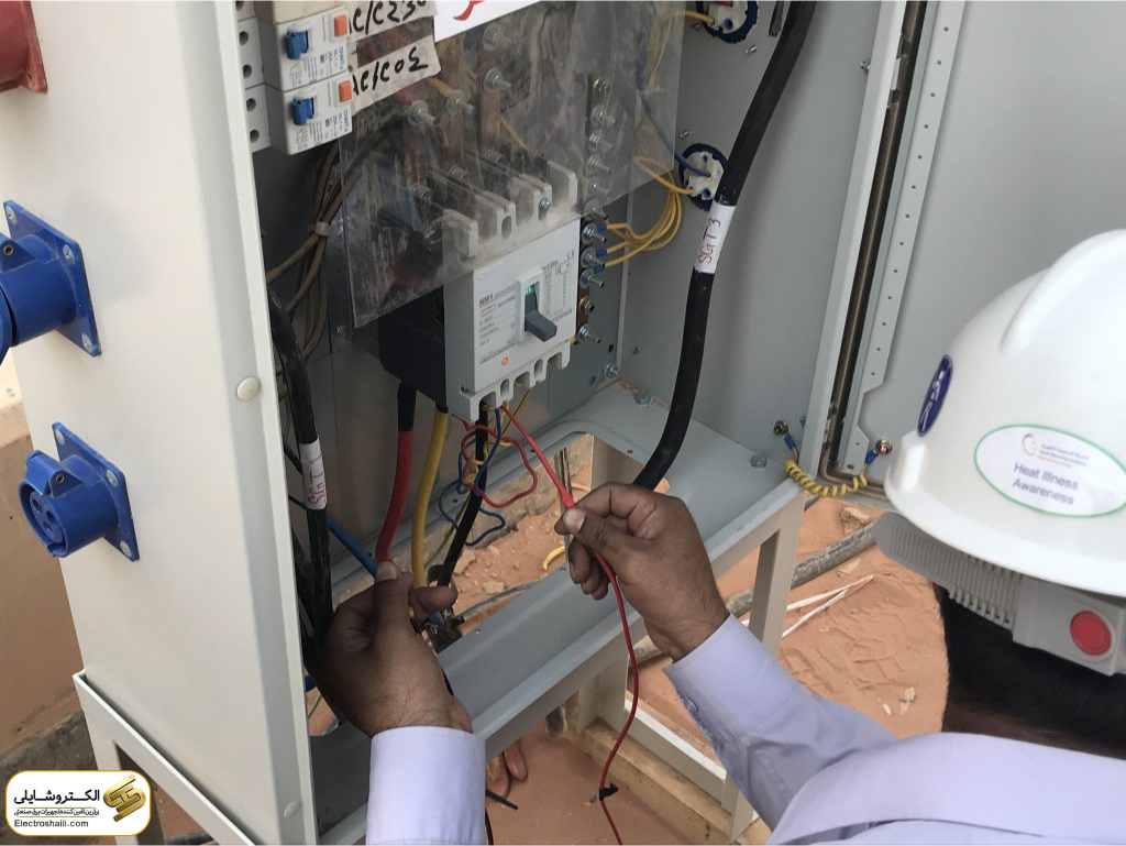
All low-voltage panels must undergo testing in the factory after manufacturing and on-site installation, and before commissioning. These tests cover areas such as dielectric properties, temperature rise, short-circuit withstand capability, continuity of protective circuits, air and creepage distances, mechanical component functionality, and protection class rating. Panel testing should be performed based on the requirements outlined in clause 8 of Standard No. 1928 of the Institute of Standards and Industrial Research of Iran.
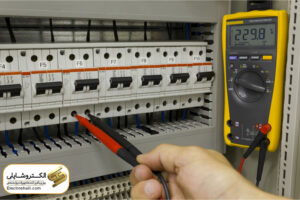
One crucial method in testing electrical panels is evaluating the performance and measuring voltages and currents in various panel components. These tests accurately assess the performance of switches, relays, and other electrical components.
Protective equipment testing is another essential part of the electrical panel testing process. These tests examine the accuracy and performance of protective devices based on standards and regulations.
Insulation resistance tests are conducted to evaluate the quality of insulation and prevent short circuits and potential electrical accidents. These tests usually include voltage withstand tests, insulation resistance tests, and continuous insulation tests.
Operational tests and trip tests are also performed to ensure the electrical panel’s performance in various conditions and in case of emergencies. These tests ensure the system’s ability to respond quickly and effectively.
Each of these testing methods serves its specific purpose, and the correct combination of these tests is of utmost importance. Regular testing as part of preventive maintenance ensures the optimal and trouble-free operation of electrical panels.
Variety of Testing Methods for Electrical Panels
In the field of testing and evaluating electrical panels, there are two important categories of tests that contribute to improving the performance and ensuring the proper functioning of panels:
A) Routine Tests: These tests can be conducted on any type of electrical panel and can also subject themselves to destructive products.
B) Type Tests: These tests are typically performed on manufactured panels to ensure that various panel components operate correctly under normal conditions and confirm their health.
First Type of Electrical Panel Test
One vital method for testing electrical panels is the use of impulse voltage. Due to switching in the network, impulse voltages are generated. For different rated voltages, tests are conducted with different impulse voltages. For example, for 12 kV, the test is performed with 75 kV, for 24 kV with 125 kV, and for 36 kV with 170 kV impulse voltages.
Short-circuit withstand current tolerance is also crucial, and panels must prove their capability against their rated short-circuit current.
The temperature rise tolerance test is conducted during the nominal current flow, and it must comply with standard values.
Additionally, the sparkover tolerance test, in case of an internal spark within the electrical panel, identifies appropriate measures to control air pressure and prevent panel component failures.
Detectors and sectioners are also tested, including impulse tests, short-circuit withstand current, and temperature rise at their connection points. Each switching and detecting equipment is tested to withstand short-circuit currents.
Basic Tests
In the basic testing process, which is conducted on most industrially manufactured electrical products, the following aspects are considered:
A) General Controls: This section examines critical dimensions of products, including paint thickness, proper and intact operation of door locks, correct adjustment of door clearances, panel protection class (IP), color of busbars, integrity of screws and nuts, and their proper selection.
B) Mechanical Controls: This part evaluates the proper functioning of keys and mechanical interlocks, insulation control, grounding system continuity, correct movement, and proper connection of cables, drawers, and other movable mechanisms, as well as the performance of drawer sectioners.
C) Electrical Controls: In this section, factors such as nominal voltage and current, control voltage of control circuits, short-circuit current, accuracy and quality of protective circuit operation, and electrical performance of all main switches and power circuit frequency test are assessed.
Insulation Test for Electrical Panel
Equipment insulation testing through specific tests can identify insulation weak points caused by mechanical damage, vibrations, temperature changes, additional frost, pollution, oil, moisture, and severe voltage changes. Devices used for these tests must have the following specifications:
Digital 5 kV Insulation Test
This device is used for testing the insulation of high and low-voltage electrical equipment and can detect weak points in insulation.
Protective and Measurement Tests
These tests are conducted to assess the performance of the protective system and include an examination of the current transformer and the detector or voltage transformer and the detector.
Measurement System Test
To evaluate the performance of a specific current measurement system, a primary current injection device is used, and then the current value is read using an ammeter. With the correct selection of current transformer and ammeter, and proper connections, the read value will synchronize with the injected current value.
Testing Primary Current Injection in Electrical Panels
The primary current injection test in electrical panels is conducted to assess the complete functionality of the protection system components. In this test, a high-current injection is required to evaluate the performance of necessary protective devices. Additionally, the operating time of the protective relay is precisely measured. This test enables the identification of incorrect connections in the current transformer or incorrect relay settings.
The desirable performance of the protection system is tested, including the adjustment of the relay’s current protection function and the current injection test using the primary current injection device.
The test includes the following steps:
– Adjusting the current protection function of the relay.
– Injecting primary current through the busbar box and increasing it through the relay setting system.
– Recording the relay’s operating time.
– Verifying the desired performance based on the relay setting system.
By conducting this test, any errors or faults in the current transformer connections, the mechanism of the detent, or the relay can be identified and rectified.
Testing Secondary Current Injection in Electrical Panels
In this test, the functionality of the protection relay is examined using the secondary current injection device. This test is conducted to precisely evaluate the performance of the protective relay and focuses solely on the relay’s performance. With current injection in the secondary, this test is simpler, requiring less current, and accurately measures the operating time of the relay.
Furthermore, other fundamental (routine) tests include:
– Power frequency voltage tests on the main circuit.
– Dielectric tests on auxiliary and control circuits.
– Measurement of the main circuit resistance.
– Mechanical performance tests.
– Verification of wiring accuracy.
– Measurement system tests.
Basic Tests for Electrical Panels
All manufactured panels undergo fundamental tests according to the IEC 298,694 standard. The conditions and specifications for these tests, as well as the required equipment and devices, are as follows:
Power frequency voltage test on the main circuit
(This test is performed for panels from 6.3 to 63 kilovolts.)
Panel Megger test
In this test, a voltage of 1000 volts is applied to the wiring in a panel, referred to as the power frequency test for the control circuit or the megger test. The goal is to ensure there are no short circuits or current leakage due to damage to the insulation coating on the wires. This test is conducted to examine panels containing control, protection, or measurement circuits.
Dielectric test on auxiliary and control circuits of the electrical panel
In this test, the secondary of current transformers is separated from ground and short-circuited, while the secondary of voltage transformers is left open. By applying power frequency voltage to the auxiliary and control circuits with a voltage of 2 kilovolts for one minute, the device is activated. The test is successful if no electrical discharge occurs. In the insulation test, weak-pressure panels are divided into two parts: electrical circuits and grounding circuits. In the first part, a voltage of 1 kilovolt is applied, and in the second part, a voltage of 25 kilovolts is applied for one minute.
Testing the electrical panel with measurement of main circuit resistance
Resistance measuring devices are used to measure the resistance of the main circuit. The measured resistance indicates the quality of the current path, and its resistance range is not specified.
Mechanical performance test of the electrical panel
In this test, the main circuit is without voltage and current. The mechanical performance of the device, such as the operation of the disconnect switch and other movable parts, and mechanical interlocks, is examined. This test is performed five times, and no adjustments are made during it. At this stage, by energizing the disconnect switch mechanism with critical boundary voltages, the accuracy of the wiring is ensured.
Testing the measurement system of the electrical panel
To ensure the proper functioning of the measurement equipment in the panel, including voltmeters, ammeters, wattmeters, varmeters, power factor meters, converters, and other equipment, specific operations are performed. Initially, current and voltage generators with specified values are connected to the panel’s measurement system according to the electrical panel’s electrical drawings. Then, the values applied by the measuring devices are displayed. These set values indicate the accuracy of the measurement systems, and if the measured values deviate from the applied values of voltage and current, necessary actions are taken to rectify issues in the measurement system.
Testing the paint thickness control with a device in the electrical panel
The execution method is as follows: the device probe is placed at various points on the painted piece, and its thickness is measured. If the paint thickness is uniform on the surface of the piece and complies with the provided specifications, it is considered an acceptable product. Otherwise, it is returned to the painting department as an unacceptable product.
– Paint thickness control is dependent on its surface.
– Parts less than 10 square centimeters are a single point.
– Parts larger than 10 square centimeters and less than 50 square centimeters are four points.
– Parts with blind spots like columns and bundles determine the paint thickness.
RAL Control Test
The color of the panels for each project selected by the client or project manager must match the chosen RAL using a RALMETER. For this purpose, one of the colored pieces, which has a hole with a diameter of 10 millimeters or similar, is placed on the RALMETER, and no color difference should be observed.
This test must be performed at the beginning of the painting process on the first piece of each project by the QC inspector. If any discrepancies are observed, necessary actions are taken to
Transformer Measurement
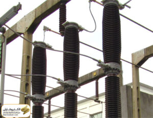
A current transformer is a device that converts high and unmeasurable currents in a line into a lower current to be both protective and measurable. In the medium voltage range, current transformers often use Cast Resin or resin casting. The main components of a current transformer include the primary winding, secondary winding, core, and resin.
For example, a 200/5 A current transformer has the ability to convert a current of 200 amperes at the input to 5 amperes at the output, which is suitable for measurement or protection equipment. Standard values for secondary current are usually 1 ampere and 5 amperes.
The specifications of a current transformer core may vary for measurement and protection purposes. The core of a current transformer can be single-core for measurement or suitable for measurement and protection equipment.
The primary specifications of each core are its accuracy class. Common accuracy classes for measurement cores are 0.2, 0.5, and 1, denoted as 0.2 M5, 0.5 M5, and 1 M5, respectively. This means that the equipment has an error of 0.2%, 0.5%, and 1% at 5 times the rated current, respectively. Common accuracy classes for protection cores may be 5P10, 10P10, and 5P15. For example, the 5P10 accuracy class means that the transformer has a 5% error at 10 times the rated current. Cores required for differential protection usually have a 5P20 accuracy class and their output power is 20 volt-amperes or more.
Example:
Ratio: 300/5-5A
Core 1: CL 0.5, 10VA
Core 2: 5P10, 10VA
In general, measurement equipment is selected based on the rated current and cannot handle currents several times higher than the rated current.
Thermal Current Effect (Ith)
Thermal current effect directly affects the copper cross-section in the transformer, significantly impacting the transformer’s price. This effect is more pronounced on the copper consumption in the secondary, as the length of the secondary copper conductor has a very high resistance.
Voltage Transformer
Voltage transformers, like current transformers, reduce the voltage value in the power circuit to a level that is measurable and comparable for protection purposes. Unlike current transformers, where the core characteristics are entirely different for measurement or protection transformers, the cores of voltage transformers for protection and measurement purposes are quite similar.
For this reason, a voltage transformer with a 0.5 accuracy class can provide accurate readings and is also suitable for over-voltage or under-voltage protection. This is because voltage fluctuations in the network are very low (+0.5% to -0.5%). Voltage transformers can be connected between phase and ground or phase to phase.
Summary
The provided texts discuss various types of tests and electrical equipment in electrical panels. These tests include insulation testing, current injection testing, dielectric testing, measurement testing, and paint thickness control testing in electrical panels. Each of these tests is used to ensure the correct performance and safety of electrical equipment. Additionally, concepts related to kiosk substations with transformers, current and voltage transformers, and their core specifications are detailed.

