Principles of Electrical Protection and Types of Protective Equipment
Electrical protection is defined as a series of safety measures implemented in electrical installations to prevent hazards resulting from electric current and to protect individuals, equipment, consumers, and electric current-carrying wires from damage. These principles of electrical protection ensure the proper operation of electrical installations by introducing various protective equipment and implementing safety standards.
Various protective equipment in this regard is dedicated to controlling and managing electrical currents, preventing imbalance, and avoiding unwanted incidents. These include protective relays, fuses, automatic switches, and thermal brakes. Protective relays operate based on different theories such as time, current, or a combination thereof, disconnecting the system from dangerous currents during hazardous situations.
To prevent these hazards, it is essential to use different types of electrical protection. This article introduces various types of electrical protection and examines tools and protective equipment that not only ensure the safety of humans and devices but also have diverse applications.
Classification of Types of Electrical Protection
In the field of electrical protection, three main categories are defined as follows:
1. Protection of Humans against Electric Shock
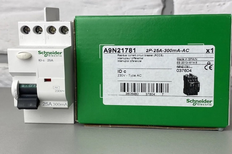
This type of protection focuses on the safety of individuals exposed to electric currents. The use of protective devices such as RCD switches and additional protection devices can minimize the risk of electric shock and safeguard the well-being of individuals.
2. Protection of Consumers and Electrical Equipment
In this area, measures are taken to protect electrical equipment and devices from the hazards of electric currents. The use of protective systems, such as supplementary protection circuits and safety equipment, ensures the achievement of this goal.
3. Protection of Wires and Cables
In this domain, attention to protecting wires and cables from various electrical hazards is crucial. Proper insulation, installation of conduits, and physical protections on wires help prevent damage to electrical systems.
Electrical Protection Techniques
In establishing electrical protection, two fundamental methods are employed to prevent electric shock. The first method is indirect protection, achieved through connection to the body of electrical equipment and implementing a grounding system.
On the other hand, direct protection also exists, utilizing life-saving devices such as RCD and RCCB switches, as well as spark detectors like AFFD. These measures prevent the occurrence of electric shock hazards, ensuring the safety of individuals and electrical equipment.
Protection against Overcurrent and Short Circuit in Electrical Systems
Overcurrent in an electrical circuit refers to an excess current beyond the nominal current of the circuit, which does not cause damage to the system. Meanwhile, a short circuit involves a low-impedance connection between conductors, such as phases or neutral, resulting in a sudden increase in current.
Various measures are taken to protect individuals and electrical equipment from the effects of overcurrent and short circuits. These include using automatic disconnection devices or limiting the maximum overcurrent. These methods serve as vital tools in preventing electrical hazards and maintaining the security of power systems.
Protective Equipment in the Electrical Domain
In the realm of power generation, transmission, and consumption, electrical equipment plays a crucial role. These include generators, transformers, and protective tools such as fuses, miniature switches, residual current devices (RCD), ground fault relays, phase fault relays, and other essential components. These devices also encompass wiring tools, devices, and power-consuming instruments. The use of protective equipment enables electrical systems to operate safely and efficiently.
Utilizing Protective Measures for Electrical Equipment and Consumers
Protecting electrical equipment and consumers is of utmost importance, as these devices are exposed to hazards such as short circuits and overcurrent. Protective measures are implemented on devices and consumers in advance, predominantly through devices like fuses, thermal relays, and miniature switches. These measures are generally placed before the device and consumer.
For household electrical devices and consumers, miniature switches are used simultaneously to protect equipment against overload and short circuits.
Protection against overcurrent and short circuits is accomplished using non-metallic switches, magnetic thermal switches, fuses, miniature switches, automatic switches, and air switches. These protective tools enhance the security of electrical systems and prevent accidents.
Unified understanding of the protection system
The protection system is a comprehensive structure, and all its components are of great importance. These components include grounding wire or protective conductor (ground), grounding connection conductor, grounding electrode, main grounding terminal, distribution panels, main and additional bonding conductors, protective equipment, protective switches, and other related components.
This system generally encompasses a wide range of actions and components to prevent any electrical hazards and potential damages. It is crucial that all components work in harmony and unity so that the system operates optimally and ensures the safety of electrical systems.
Ground protection components in electrical systems
The protective conductor or ground in an electrical system plays a vital role in connecting the body of electrical devices to the ground. This connection is made through the ground connection busbar or protective grounding terminal in secondary distribution panels and the connection of two grounding conductors in secondary and main distribution panels. Additionally, the connection of the grounding busbar in the main distribution panel to the main grounding terminal is used.
Ground connection conductor refers to a part of the grounding wire that connects the grounding electrode to the main grounding terminal. The grounding electrode, in turn, refers to one or more pieces of conductor in direct contact with the ground and having electrical connection with it.
Ground electrodes are divided into three categories based on their shape and placement in the ground: plate electrodes, vertical electrodes, and horizontal electrodes. Moreover, electrodes are made of various materials and shapes.


– Copper rods: Copper rods are driven into the ground with a hammer and have sharp steel tips to facilitate penetration into the ground.
– Copper plates or plate electrodes: In humid areas, the minimum soil coverage from the top edge of the plate should be 1.5 meters.
– Metal sheath or armor of underground cables: The sheath and armor of cables in the post are connected to the neutral and are used as a grounding electrode and ground wire.
To reduce ground resistance, in many cases, a set of rods is used as individual electrodes. It should be noted that the resistance between the electrode and the ground depends on the specific resistance of the ground, which varies based on the ground material and its moisture content.
Electrical protection using grounding wire
In the electrical protection method using a grounding wire, parts of devices that do not have electrical connection to the power supply network are connected to the ground via a wire. When the body in the electrical device is not connected, the protected parts of the device are equipotential with the ground. When the electrical parts are connected to the body, a current flows from the device’s body to the star point of the transformer network – through the wire connected to the ground and the ground.
In cases where the wire insulation is damaged, and a dangerous current flows through the connection to the body of the device, connecting to the ground effectively prevents such accidents. If a person comes into contact with the faulty device, the current will flow to the ground, and the amount of current passing through the body becomes part of the main dangerous current. By installing a low-resistance ground wire, this current will not reach a dangerous level of 0.030 amperes.

The cutoff current value must be sufficient to quickly disconnect the fuse and cut off the contact voltage. This current is called the cutoff current, and its value depends on the rated current of the fuse placed in the device’s path.
The diagram below illustrates how to use the ground protection system for consumers.
Protection using Neutral Wire in TN System
In the neutral protection system, unlike using the ground wire, the network neutral wire (MP) connected to the device’s body is used instead. In this system, similar to the ground protection system, measures are taken to quickly disconnect the protective device’s body in case of a connection, for example, through a fuse. In this system, even if the neutral wire is disconnected for some reason and the consumer is not connected to the body, a potential difference (contact voltage) is created. This potential difference is equal to the potential difference between the phase and ground in the device, so that if a person touches the device while touching another conductor connected to the ground, a dangerous current passes through his body. This system protects individuals against electrical hazards and reduces the risk of dangerous current in case of neutral wire disconnection.

In this scenario, the Protective Earth – Neutral (PEN) common conductor is simultaneously connected to the device’s body and neutral terminal.

For better protection in electrical networks, it is suitable for neutral protection to be performed by a separate neutral wire from the main ground wire. To reduce the likelihood of neutral protection wire disconnection, special wires with cross-sectional areas less than 10 square millimeters, which have specific electrical protection standards, can be used.
In a network where one or more consumers are protected by the ground wire and other consumers are protected by the neutral wire, when a connection to the device’s body occurs in a consumer (protected by the ground wire), at the same moment, a potential difference between the body and ground is created in consumers protected by the neutral wire, which may be dangerous.
Protection of devices through low voltage utilizes technologies that use voltages less than 24 volts to ensure device safety. This voltage is provided through a transformer with two separate winding wires.
It is worth noting that devices protected by this system do not need a terminal for the protective wire, and their current circuit should not be connected to the ground or neutral wire and even to other devices operating at high voltage.
Also, in low-voltage devices, make sure they have two standard outlets (220 volts) so that they cannot be connected to high-voltage outlets.
Protection through the isolated transformer method also uses a transformer to supply the consumer’s voltage, with the difference that in this method, the consumer’s voltage is higher than 60 volts and may even be equal to the network voltage.
Finally, protection through the life guard switch occurs through a housing that has a magnetic switch and a current converter. This system uses the magnetic relay current from the current converter for device protection.
In the absence of body connection or the danger of electric shock to the person in the consumer, the input and output currents of the consumer are equal and in opposite directions. This contradiction of currents creates a mutual magnetic field, and no magnetic flux from the converter core passes. This situation does not induce any voltage in the secondary winding wire of the converter, and the magnetic relay does not operate.
However, in case of body connection in the consumer or the danger of electric shock to the person, a current from the ground passes through the network transformer towards the transformer’s zero point. This increases the current flowing through the loop inside the consumer towards the transformer, and this current difference with the current returning to the network creates a current in the core. If this current difference is significant, the relay is activated and disconnects the main switch.
Protection in Electrical Panels
For effective protection in electrical panels, creating a system based on safety and engineering standards is essential:
– First, all panels must be equipped with an adjustable main switch key or an automatic key as a disconnecting source.
– The protective device of each panel, such as fuses or miniature switches, must be selected separately and according to the needs of the panel. The rated current of these protective devices must match the total consumption current of the panel.
– If the main switch of the panel is under load, the fuse should be placed on the consumption side of the switch (after the switch) so that in the no-load condition, it is possible to replace the fuse.
– The power supply circuit of control and measurement devices such as signal lamps, ammeters, wattmeters, or power meters should also be equipped with special protective devices.
– If miniature switches are used, be sure to install a series of fuses or current-limiting switches in the panel or upstream panel. These fuses are known as backup fuses, and their selection depends on the rated current of the disconnecting switch or miniature switches.
– If the rated current of the disconnecting switch or miniature switches for short-circuit conditions is equal to or less than 1/5 kiloampere, consider the rated current of the backup fuse less than or equal to 63 amperes. If the rated current of the disconnecting switch or miniature switches for short-circuit conditions is equal to or less than 10 kiloamperes, consider the rated current of the backup fuse less than or equal to 100 amperes.
Electrical Protection through Fuses
Fuses act as an effective means of protecting electrical circuits. These devices are placed in series at the beginning of the current path of different phases of an electrical circuit. The main function of a fuse is to protect wires, cables, measuring devices, transformers, electric machines, and other consumers against sudden increases in current and short circuits.
Varieties of Fuses
Fuses are divided into different categories based on their voltage and operating principle:
– Melting or fusible thermal fuses
– Alpha or automatic fuses
– Miniature fuses
– Blade or cartridge fuses
Important Points in Installing Fuses in Circuits:
1. The location of the fuse at the beginning or end of the line can have different effects. If installed at the beginning of the line, both the consumer and the line are protected against short circuits and increased current. In contrast, installing a fuse at the end of the line and near the consumer only protects the consumer.
2. In the installation of fuses, especially in distribution panels, fuses at the beginning of the line should have a higher rated current than fuses at the end of the line. Also, slow-blow fuses should be installed farther from fast-blow fuses.
3. For short-circuit conditions in a device, the fuse should act as close as possible to that device.
4. Fuses used based on the motor starting current should be selected to be 1/5 to 2/5 times the rated current of the motor. For squirrel-cage asynchronous motors directly connected to the network, a slow-blow fuse with a rated current of 1/5 to 2/5 times the rated current of the motor can be used.
5. In squirrel-cage asynchronous motors with wound rotor, which are connected to the starter in star or delta, a slow-blow fuse can be used for protection.
6. At the moment of connecting the transformer to the network, due to the saturation of the core, a large current passes through the primary winding. Therefore, a slow-blow fuse with a current equal to twice the rated primary current can be used, and in the secondary, a slow-blow fuse with the rated current.
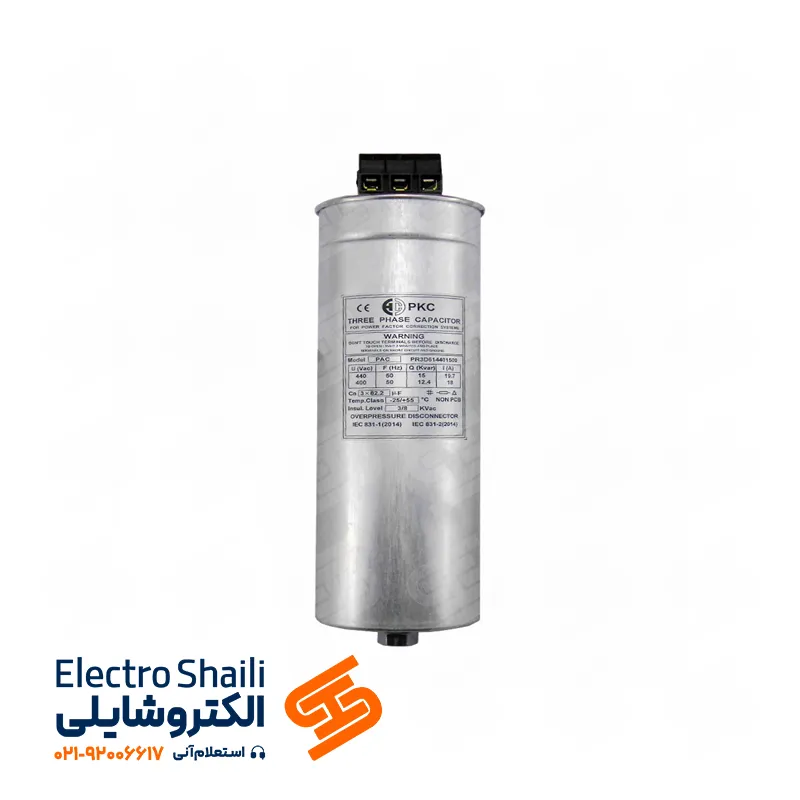
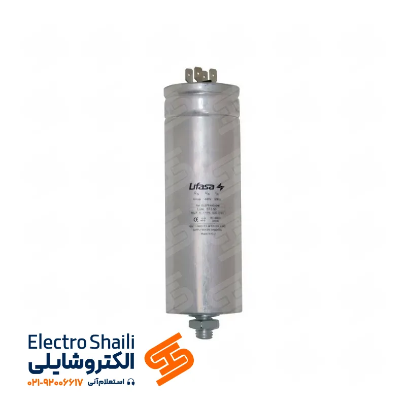
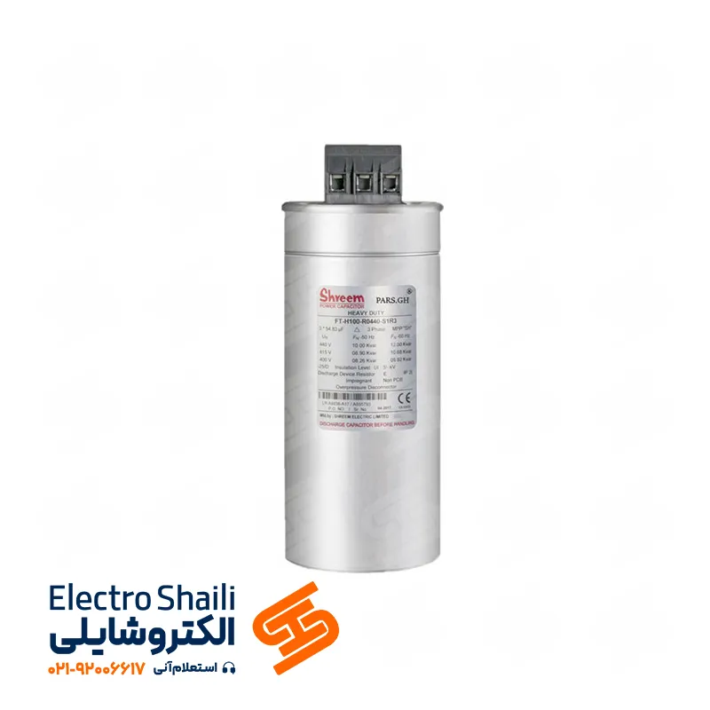
7. When connecting capacitors to the load or network, a large current flows through the circuit at the moment of connection. Therefore, a slow-blow fuse with a current equal to 1/5 times the rated current of the capacitors can be used for circuit protection.
Miniature Switch: Features and Applications
The miniature switch is an important electrical device that is structurally similar to an alpha fuse. This switch consists of three main parts:
1. Magnetic Relay: This part of the miniature switch is used to disconnect the circuit in case of a short circuit. The magnetic relay’s magnetic features, including reliable performance and prevention of potential hazards, make it a superior protective option.
2. Thermal or Bimetal Relay: This part of the miniature switch is responsible for preventing hazards related to overload. The thermal relay, by controlling the temperature and preventing the increase of heat due to overload, safely disconnects the circuit. The bimetallic nature of this relay adds to its unique features.
3. Switch: The third part, which is the switch itself, plays a role in connecting and disconnecting electrical circuits. The miniature switch has a very small and lightweight structure, making it an ideal choice for limited spaces and applications that require easy access to the switch.
Miniature switches are used as an efficient solution in electrical systems for protection and current management. By combining magnetic and thermal capabilities, these switches ensure optimal performance and continuous safety.
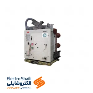
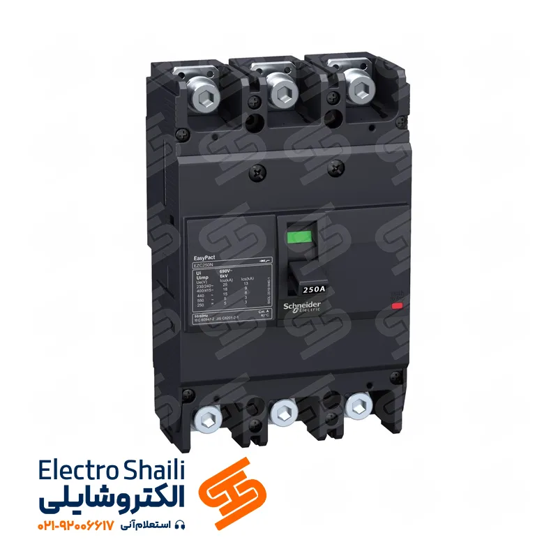
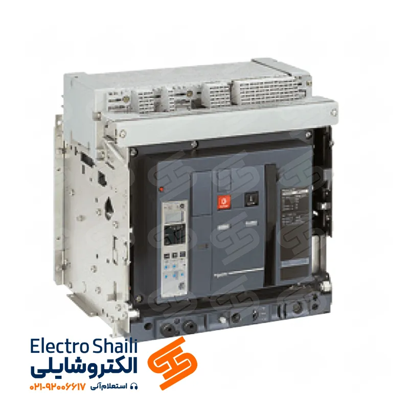
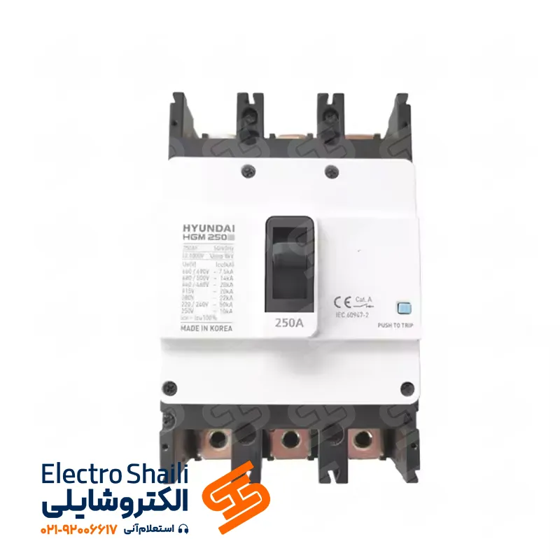
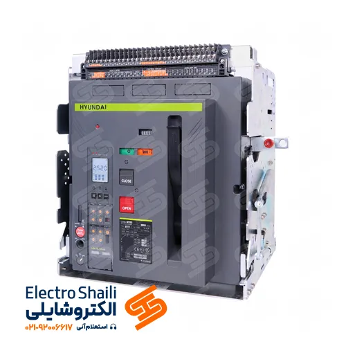
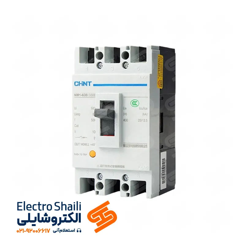
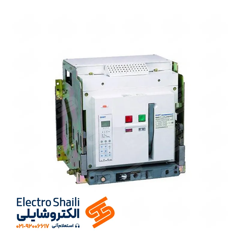
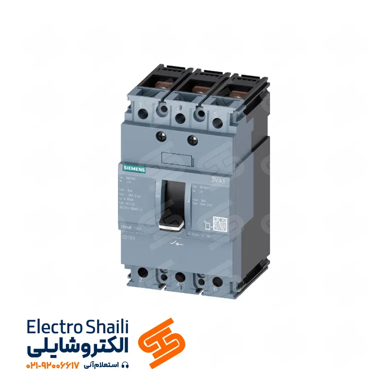
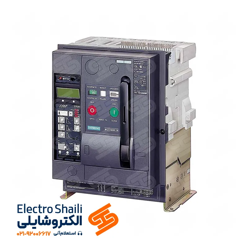
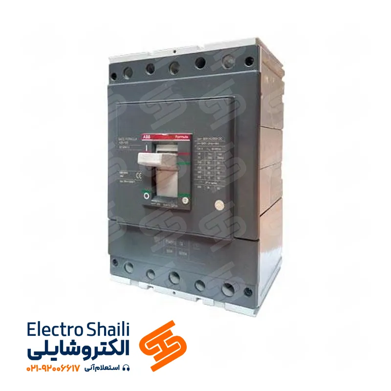
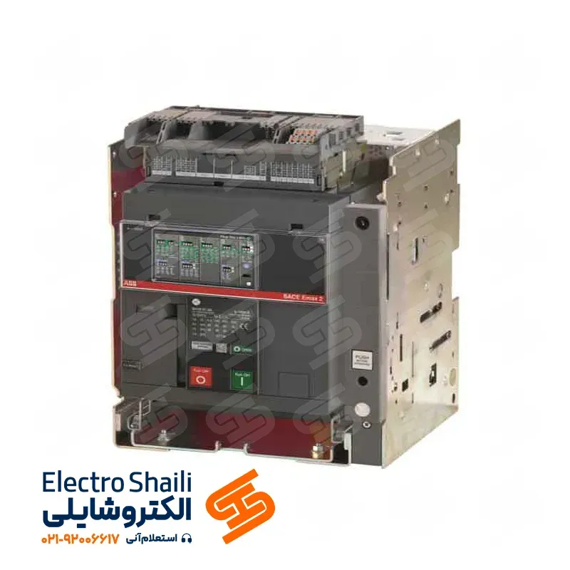
Compact MCCB Automatic Switches: Ensuring Safety and Flawless Operation
Compact or Molded Case Circuit Breakers (MCCB) are used as essential components in electrical systems. These switches are designed to protect circuits and devices from the dangers of short circuits and overloads. Overload protection in these switches involves the use of a thermal relay for managing current increases in the circuit.
Automatic switches are used to prevent electric shock in the face of a short circuit between phases and the ground or earth (PE), or between the protective phase (PEN) and the neutral.
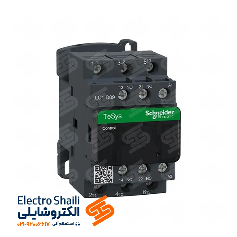
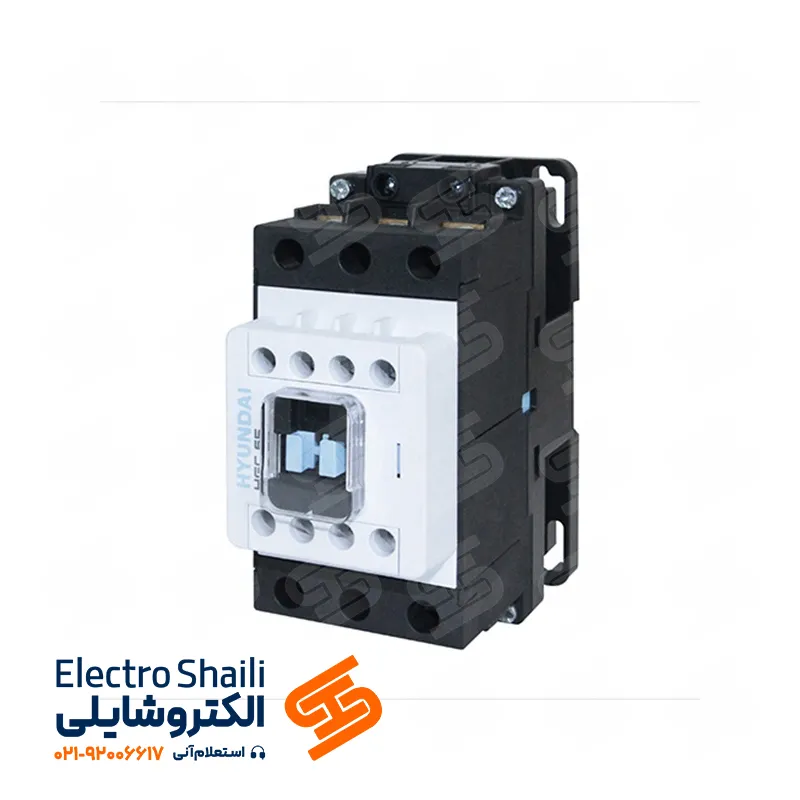
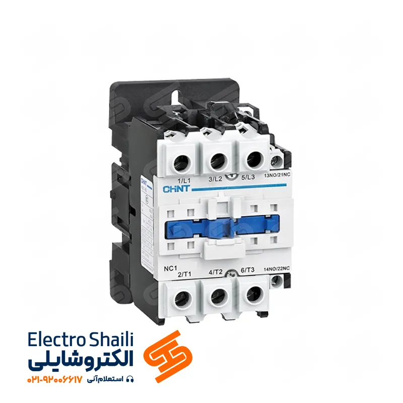
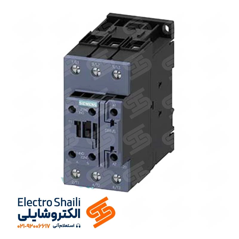
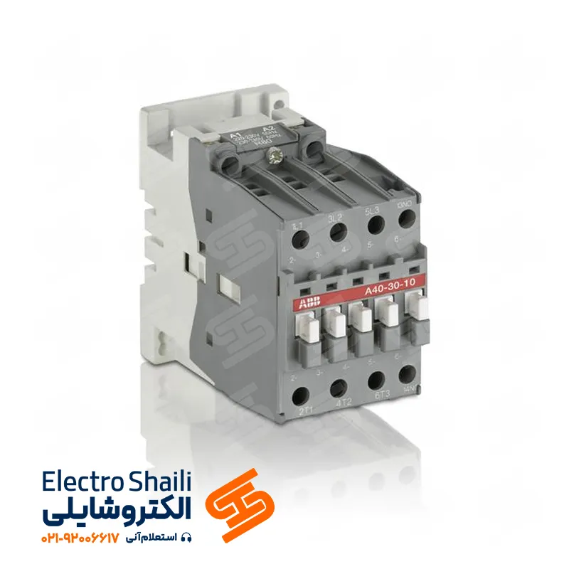
Magnetic Switches (Contactors): Integrated Control and Protection
Contactors or magnetic switches are vital tools in the transmission and distribution of electric power. These key components are widely used for operations such as switching, controlling, and commanding circuits. Depending on consumer needs and circuit characteristics, these switches are employed.
To protect against overload, contactors are usually used in conjunction with thermal relays. Additionally, to deal with the hazards of short circuits, fuses or automatic switches should be used on the input side (power supply) of the contactor.
Alongside contactors, various types of relays can be utilized, including voltage control relays (Overvoltage or Undervoltage), phase control relays, and other auxiliary relays to enhance system efficiency and precise control.
Electric Motor Protection Circuit: Ensuring Optimal Performance
Protecting electric motors is crucial in electrical systems, and various equipment is used for this purpose to ensure the optimal and flawless performance of these motors.
1. Underload Disconnect Switch: The use of underload disconnect switches, such as rotary switches, is the initial step in motor protection. These switches provide easy and adjustable motor disconnection and connection capabilities.
2. Short Circuit Protection with Fuses: To address the dangers of short circuits, fuses with specified power depending on the motor’s rated current are used. These fuses ensure effective protection in all motor startups.
3. Contactor: Contactors are used to disconnect and connect the motor and control its operation. These key components have the capability for precise control and connection to control systems.
4. Thermal Relay: To protect against overload, a thermal relay is connected to the contactor. This relay, by monitoring the motor’s temperature and automatically disconnecting in case of abnormal temperature increase, protects the motor from hazards.
5. Phase Control Relay: A phase control relay is used for monitoring and controlling various motor phases. This relay, with high accuracy and adjustable settings, provides enhanced safety and efficiency in motor systems.
Motor Protective Switch: Strong Protection with a Combination of Thermal and Magnetic Relays
The motor protective switch, as an intelligent alternative to underload disconnect switches, fuses, and thermal relays, provides all necessary features with adjustable capabilities.
This switch is a combination of two crucial elements, thermal and magnetic relays, providing comprehensive protection to the motor. By setting the relay to a specific current (approximately 1.5 to 1.8 times the rated current), it immediately activates the thermal element and disconnects the circuit in case of current exceeding this limit. Additionally, in the event of a short circuit, the magnetic release of this switch rapidly acts to protect the motor from potential hazards.
The motor protective switch protects the motor against two types of currents:
1. Thermal Current: This type of current occurs under overload conditions when the motor tolerates more current, leading to an increase in its temperature.
2. Magnetic Current: This type of current occurs under short circuit conditions between two phases or the connection of the body to the phase, or the connection of the phase to the neutral. This current also leads to an increase in temperature in the motor.
Bimetallic Thermal Relay: Protective Ring for Electric Motors
The bimetallic or thermal relay acts as a vital tool in protecting circuits, especially motors. This device, by combining two dissimilar metals that undergo shape changes under additional heat, momentarily disconnects the circuit.
A three-phase thermal relay has three contacts for the main current to the consumer and two control contacts. The closed control contact with numbers 96-95 is involved in disconnecting the control circuit under overload, while the open control contact with numbers 98-97 issues warnings and notifies the operator about the disconnection of the bimetallic relay.
Bimetallic relays have the capability to work in various currents, and their permissible current can be adjusted with a set screw, allowing for a change in their performance. In cases of using bimetallic relays for motor protection, their current is adjusted to the motor’s rated current, providing the ability to protect the motor against overload.
Important Points:
– The relay should not disconnect the circuit at the rated load.
– If the current passing through the bimetallic relay is more than 5% of the set current, it should disconnect the circuit for more than 2 hours.
– If the current passing through the bimetallic relay is 20% more than the set current, it should disconnect the circuit in less than 2 hours.
– If the current passing through the bimetallic relay is more than 50% of the set current, it should disconnect the circuit in less than 2 minutes.
Magnetic Relay: Magnetic Fields for Protecting Electric Machines
The magnetic relay is a powerful tool used to protect electric machines against short circuits. This relay is constructed with a fixed iron core, a movable core, and a coil.
When a short circuit occurs in the circuit, the current passing through the coil increases, causing the movable core to connect to the fixed core. This action opens the relay contacts, rapidly disconnecting the circuit.
Final Words
This article explored the importance and applications of electrical protection tools such as fuses, automatic switches, thermal relays, and magnetic relays. We carefully examined key points related to the installation and use of these tools. Additionally, emphasis was placed on the importance of properly adjusting these tools and technical considerations for effective protection of electrical circuits and motors.