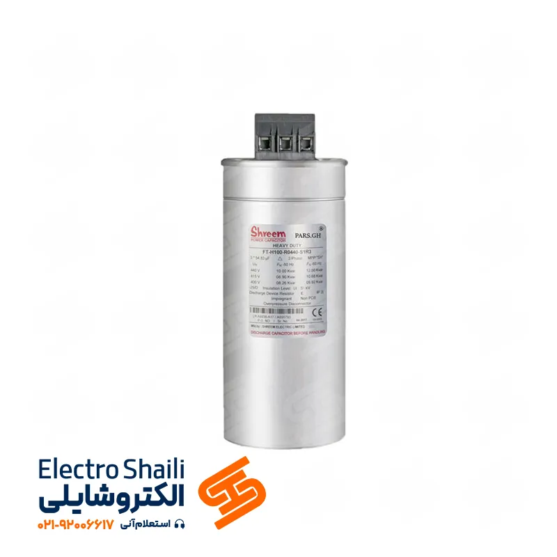
Power Factor and Reactive Power Compensation Solutions
In the advanced world of electrical technology, power factor correction holds significant importance. Through the use of capacitor banks and advanced technologies, this process manages everything from minimizing switchgear switching transients to improving efficiency in various electrical systems. Switching transients in capacitor banks indicate complex electrical phenomena associated with sudden voltage increases and current surges. This article explores various compensation methods, from correcting inactive and active power factors to group compensation, examining different aspects and the importance of this process in enhancing the efficiency of electrical systems.
The production of capacitor panels is also a crucial aspect in this field. These panels, using capacitors tailored to the system’s needs, enhance power factor correction. Additionally, comprehensive information regarding capacitor installation, ventilation, and protection within the panels is discussed here. This broad perspective on various aspects of power factor correction underscores the significance of this technology in optimizing the performance of electrical systems.
Power factor, also known as power factor or cosine phi, refers to the ratio of active power or real power to apparent power. Let’s delve into the definition of power factor:
What is Power Factor?
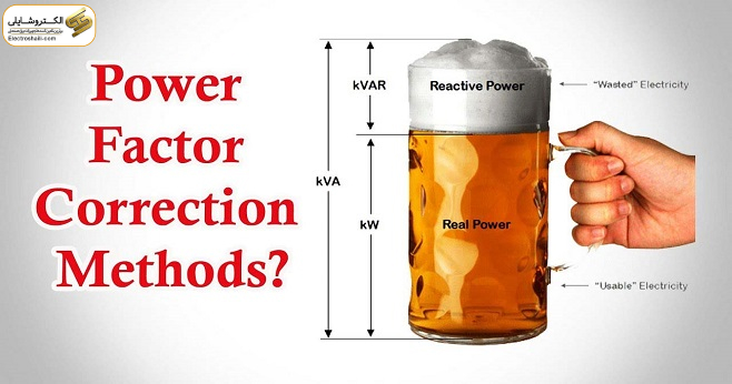
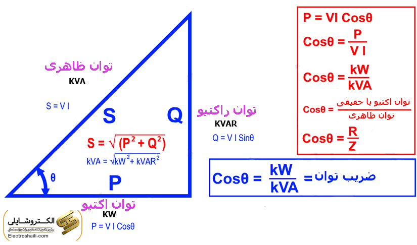
In the examination of energy consumption, three common types of power exist: apparent power (S), active power (P), and reactive power (Q). Active power is the same as real power and is represented in watts (W), indicating the power of resistive loads.
Reactive power is an imaginary power used for comparing the power of inductors and capacitors. Also, apparent power is the result of vector addition of active and reactive power. Increasing reactive power through capacitors leads to increased energy required for charging and discharging capacitors, but ultimately, this power has no consumpti
Concept of Apparent and Reactive Power Vectors, and Definition of Leading and Lagging Phase
As mentioned in previous articles on electroshaili, apparent power is the result of combining active power and reactive power. Let’s delve deeper into the concept of power vector.
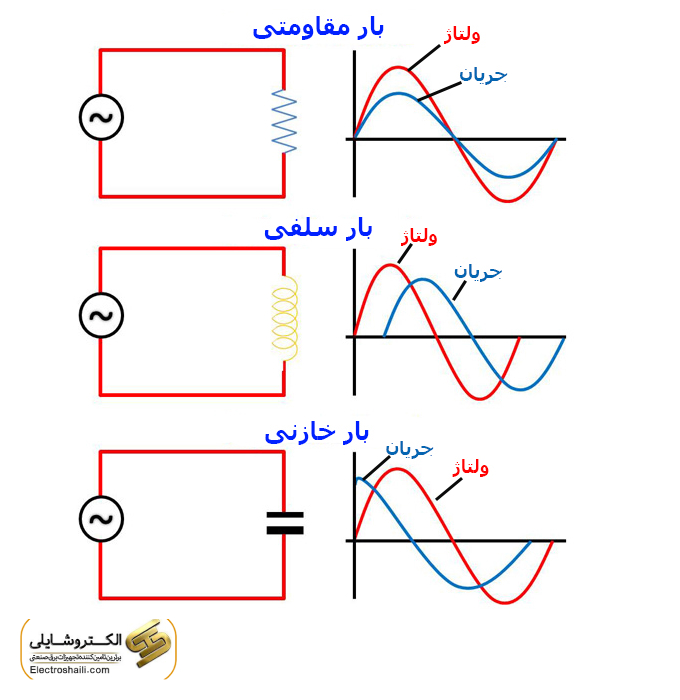
In a circuit with a resistive load where the voltage and current are in phase, but in a circuit with a reactive load (such as a capacitor or inductor), the inductor and capacitor do not consume energy; instead, they occupy network capacity as they draw current. The capacitor leads the current, meaning it generates lagging current (for an inductor), while the inductor consumes lagging current. In the capacitive load waveform, the current leads the voltage.
In electrical systems combining resistive and reactive loads, the components of active power and reactive power are introduced as total power or apparent power and are represented in kilovolt-amperes (KVA).
An angular difference is created between voltage and current, and both these parameters are considered as vector quantities. Since power is the result of multiplying voltage and current, power is also considered a vector parameter.
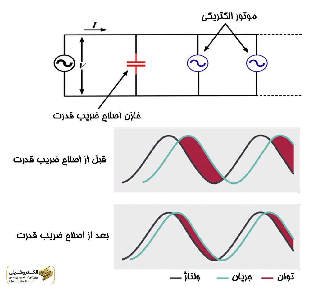
If the angle between the voltage and current of the consumer decreases (increasing the power factor), the consum
ed active power approaches the apparent power, resulting in a decrease in the consumed reactive power. One of the methods to improve this angle is to use a capacitor bank, which will be fully explained later.
Optimizing the power factor and exchanging the power factor in organizing electrical energy consumption is among the goals of the Ministry of Energy. These actions are subject to laws and regulations aimed at improving the power factor and determining tariffs related to energy consumption.
As the power factor of consumers increases, the required current for constant power consumption will decre
ase. These changes lead to reduced losses, reduced voltage drop, and increased capacity of transmission lines and transformers. On the other hand, with proper management of electricity tariffs, consumers can be directed towards consumption during off-peak hours.
Here, the importance of optimizing the power factor and determining electricity tariffs to free up the capacity of distribution and transmission networks, as well as reducing the costs of energy consumption for subscribers, is highlighted.
Many electrical devices and consumers require reactive power to perform their tasks, such as electric motors converting electrical energy into mechanical energy. Additionally, power systems, voltage stabilizers, induction furnaces, and electric arcs require reactive power. However, this power leads to an increase in network current, voltage
drop, and power losses in the path.
It is essential to understand the accurate concept of the power factor and its effects on the system and then address the methods of improving the power factor and the necessary equipment for its compensation.
Energy Price Tariffs
In calculating energy costs, maximum consumption, active energy, and reactive energy are considered separately. In most contracts, the maximum reactive power consumption is considered up to 50% of active energy consumption.
Reactive power consumption incurs costs only if it exceeds 50% of active energy consumption, and this consumption corresponds to a power factor of 0.9. For calculation purposes, it is recommended to consider a higher figure, such as 0.92, to have the necessary reserve power for capacitors.
Energy Demand Rate Tariffs
In this case, consumption is based on the maximum power in a specific month. If apparent power, not active power, is considered as the basis, it is recommended to select the capacitor amount in a way that Cosɸ is equal to 1.
Combining Components for Power Factor Correction Using Capacitors
In the power factor correction process, industrial capacitors are divided into two categories: low-pressure and medium-pressure. Industrial capacitors with low pressure fall into the following categories:
Capacitors with a voltage less than 1000 volts
Dry capacitors
Connection in either single-phase or three-phase with a delta connection
While medium-pressure capacitors fall into the following categories:
Capacitors with a voltage exceeding 1000 volts
Oil-filled capacitors
Connection in either single-phase or three-phase with a delta connection
Specifications of Low-Pressure Capacitors
Low-pressure capacitors are defined based on standards IEC70, VDE0560-Din4800-isir2781. These specifications include nominal voltage, nominal current, nominal power (VAR capacity), active losses, ambient temperature, cooling temperature, maximum and minimum operating temperature of the capacitor, and the type of connection to the network. Capacitors are categorized into 40+/40-, 40+/20-, 40+/10-, and 45+/10- ranges.
Regarding three-phase capacitors, they can be connected in Y (star), ∆ (delta), Y (star with zero point), or lll (three-section without internal connections).
The unit power of three-phase capacitors should be mentioned as the total power of three phases. Also, the fuse capacity installed in the capacitor supply path should be at least 1.5 times the capacitor current. If a contactor is used, its capacity (after applying temperature coefficients) is obtained as 1.25 times the maximum current.
For safer protection against short circuits, HRC fuses or fuses with a 1.5 times rating of the nominal current of the capacitor are used. In low-voltage conditions and small loads, power control can be manually adjusted.
For automatic control and adjustment of active power, power measurement relays, current-sensitive relays, or timers can be used. In small industrial consumers and group compensators, the use of a current relay is recommended.
In uniformly and predictably loaded situations, a time relay can be utilized. The best method of control is a relay sensitive to reactive power. The capacitor step stages range from 3 to 19 steps and depend on load conditions.
Common capacitor power values in KVAR are as follows: 5 – 10 – 12.5 – 15 – 20 – 25 – 30 – 40 – 50 – 60 – 100.
The Role of Fuses in Power Factor Correction
In the capacitor bank section, the protection of the system is highly important. To counter the risks of short circuits and excess current, High Rupture Current (HRC) fuses are employed. The selection of fuse breaking currents should be done according to relevant standards and is usually in the range of 4.1 to 5.1 times the nominal current of the capacitors. HRC fuses have very high breaking capacity and are used for the protection of capacitor banks.
Due to their rapid and effective response to short circuits and sudden increases in current, HRC fuses provide efficient breaking capability. For the protection of capacitor banks, Cardi or Sexton fuses are commonly used. These fuses ensure fast and effective interruption of current and ensure that any damage or fault in the system is minimized.
The Role of Discharge Resistors in Power Factor Improvement
To improve power factor and reduce voltage across the terminals of power factor correction capacitors after they are disconnected from the circuit, discharge resistors connected to the capacitor terminals are used. The value of these resistors is variable relative to the power of the capacitors.
These resistors must be capable of reducing the voltage safely within 3 minutes after the capacitors are disconne
cted (less than 75 volts). In specific situations where the capacitor is directly connected to electric motor wires, there is no need for discharge resistance, and precautions should be taken to prevent the motor from completely disconnecting from the capacitor-charged sections. According to the standard, capacitors must be charged to a maximum of 10% of the nominal voltage for reconnection to the circuit.
The discharge resistance is calculated by the capacitor manufacturer based on the capacitor power and is connected to the capacitor terminals during unit production. Additionally, discharge time information is specified on the capacitor plate. In cases where rapid discharge of the capacitor is required for circuit switching, a rapid discharge circuit is used instead of a resistor.
Using Switching Thyristors for Power Factor Improvement
In situations where rapid changes in power factor are needed, it is better to use switching thyristors instead of capacitor contactors. These thyristors, along with a rapid discharge circuit, are connected to the capacitor and can introduce the capacitor into the circuit within 5 milliseconds after the capacitor is disconnected, improving the power factor.
Using Intelligent Regulators in Capacitor Banks
Moreover, by using intelligent regulators, you can easily obtain a lot of information from the circuit. These intelligent regulators are designed and built in two models, 6 and 12 steps, for managing capacitor banks. The advantages of using intelligent regulators include voltage, power, load current, reactive current, voltage harmonic distortion, power factor, capacitor connection steps, the number of times capacitors are disconnected and reconnected, recording alert dates, and measuring the ambient temperature inside the electrical panel.
This device introduces the capacitor into the circuit (or removes it from the circuit) by measuring the power factor
of the load, as needed (in a stepped manner). In other words, by measuring the voltage and current of the consumer, the power factor is calculated, and based on the desired power factor (usually 0.9), the required reactive power is calculated. The output of the regulator introduces suitable steps into the circuit (or removes them) based on this calculation.
If the total reactive load of the capacitor is Q, it can be divided into smaller steps q. However, increasing the number of steps precisely improves performance but increases the number of contactors and other equipment, which increases costs.
Capacitor Contactor in Capacitor Panel
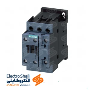
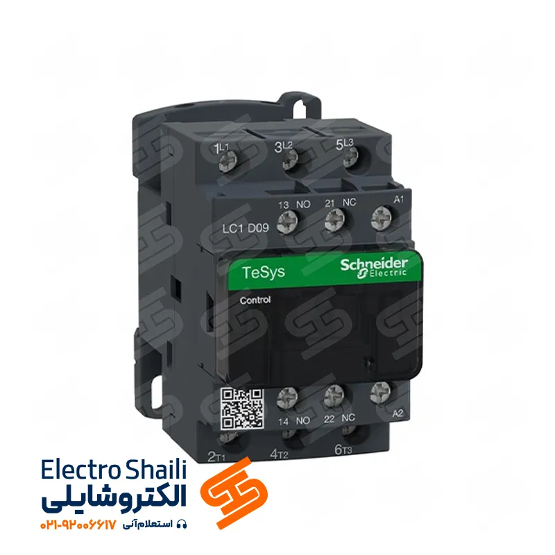
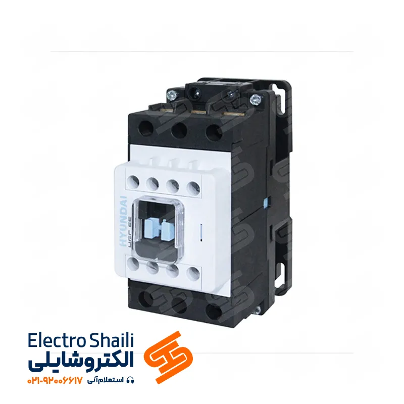
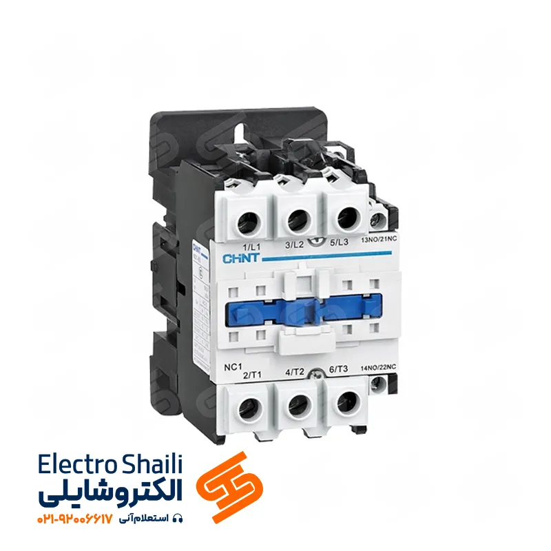
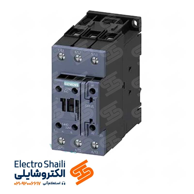
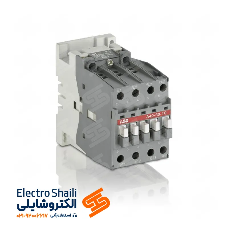
In a capacitor panel, a capacitor contactor is used as a crucial device for power factor correction. Due to the very high current when capacitors are connected, the use of ordinary contactors can lead to premature failure of the contacts.
For each capacitor to enter the circuit, a capacitor contactor is used. These contactors can be introduced into the circuit by an intelligent regulator. For example, if we have 9 capacitors with a capacity of 25 KVAR each, we will use 9 capacitor contactors and one 8-step regulator. Each capacitor should have a separate fuse, and only one control circuit is used to con
trol the capacitor bank.
The first two capacitors enter the circuit, and then the remaining capacitors are added to the circuit in pairs. After capacitors 1 and 2 enter the circuit, capacitors 3 to 8 are added to the circuit one by one.
Calculating Power Factor in Electrical Panel
In the calculation of power factor in the electrical panel, the cosine of the phase angle between current and voltage is used to calculate apparent and effective power components, voltages, and currents. The power factor is usually written for electrical loads. In networks designed for apparent power, an effort is made to minimize apparent power. Installing appropriate capacitors in parallel with consumers redistributes part of the reactive power between the capacitor and the consumer, reducing reactive network loading. With compensation, the power factor in the network becomes one, and only effective current prevails.
Ampermeters and power measurement devices are usually installed in the main panel, and clamp meters can also be used. Necessary measurements are performed in the input feeder or output feeders of the main substation.
Simultaneous measurement of network voltage increases calculation accuracy. Also, the nominal voltage can be considered as 380 or 400 volts. Using voltage (U), apparent current (Is), and power factor, active power can be calculated. To obtain reactive power taken by the capacitor (Qc), the difference between reactive power before compensation (Q1) and after compensation (Q2) is used. Therefore:
Qc = Q1 – Q2
Switching Transients in Capacitor Bank
In fact, when capacitors are connected to the circuit, they generate switching transients, usually classified as a surge current and a sudden increase in voltage.
Surge current is a phenomenon that occurs at the moment capacitors are connected to the circuit. The impedance provided by the capacitor is naturally very low and resistive. This leads to the creation of a surge current that can be up to 50 to 100 times the nominal current passing through the capacitor; the reason for this is that the transformer impedance only resists current flow in the resistance against the magnetic flux when turning on the capacitors.
This issue becomes complex when using parallel capacitor banks, which may lead to switching transient currents to a level more than 200 to 300 times the nominal current. This surge current is a result of the discharge of pre-charged capacitors connected in parallel with it.
When turning off (disconnecting) capacitors, due to the stored charge in them, a sudden increase in voltage will occur more, which may cause sparks at the terminals. When a capacitor is turned off, it retains electrical charge in itself and is discharged by discharge resistors. The discharge time is generally between 60 to 180 seconds.
Until effective discharge is performed, capacitors cannot be returned to the circuit. Any re-closure of the capacitor before complete discharge increases the surge current.
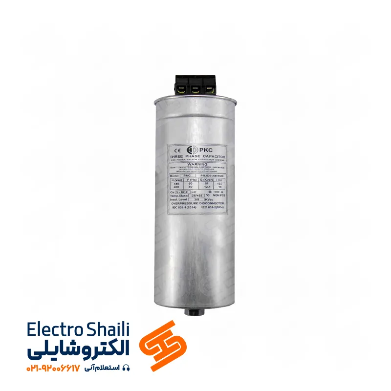
read more about PKC Capacitor
How to Improve Power Factor?
Power factor correction can be done actively and passively. Passive correction, a simple solution for improving power factor in linear loads, primarily utilizes capacitor banks for this purpose.
Although this method is widely used due to its simplicity and low cost, its effects on improving active power factor are limited. In this method, adding or removing capacitors from the circuit leads to the generation of harmonic currents, which is a weakness and one of the reasons why the use of power electronics equipment or synchronous condensers (for active power factor correction) is still prevalent.
Active power factor correction utilizes a power electronic system that controls the amount of current consumed by each load to bring the power factor as close as possible to its maximum value. This system refers to four corresponding methods of power factor correction: individual correction, centralized correction, group correction, and mixed correction.
1. Individual Power Factor Correction
Reactive power compensation is more economical for transformers, welding equipment, lightly loaded or long-cable motors, or large motors that operate continuously. In this case, capacitors are directly connected to the load either directly or through switches. Eliminating reactive power from the internal network is one of the advantages of this method. However, the higher number of capacitors for a set due to the lack of synchrony results in higher costs, making it a disadvantage.
In the simplest model, a capacitor with the appropriate value is installed in parallel with each inductive load. This significantly reduces the burden on wires and cables. It should be noted that the capacitor is only used during the active operation time of the devices. Also, installing capacitors for individual device compensation is not straightforward. Individual compensation is applied to continuously operating motors, lightly loaded motors, or those with long cables, and compensation for reactive power is load-free transformers.
2. Centralized Power Factor Correction
When a large number of small and medium loads that are not continuously in the circuit need correction, capacitors are centrally connected to the main bus, controlled manually or automatically. This method is similar to individual compensation but is more economical. It is also usable for all voltages. However, in distribution lines, there is protection against short-circuit currents between the bus and the consumption points, and each capacitor requires an HRC fuse. Also, in transformers with open-delta connections, capacitor discharge is necessary after each disconnection.
The entire centralized compensation is installed at the entrance of the low-voltage network. This way, all the required reactive power is covered. The total capacitor power is divided into multiple steps and is introduced or removed from the circuit through contactors by a reactive power regulator, depending on the load status.
This method is often more considered today because centralized compensation can be easily controlled. Modern reactive power controllers can always monitor the status of switches, power factor, reactive current, and harmonics present in the network. In general, due to considering synchrony in the entire plant, less capacitor power is needed compared to individual or group compensation.
In this method, reactive current of wires and cables used in the internal network is not significantly reduced by compensation. That is, if the cross-sectional area of cables and wires in the factory does not create a problem, centralized power factor correction is always useful.
3. Group Power Factor Correction
In large installations such as industrial factories with a central motor room, capacitors are installed in groups near the power substation or main panel, controlled by power factor correction regulators. The advantages of this method include the practical use of the installed capacitors and attention to synchronous factor.
Additional costs such as installing a regulator are disadvantages of this group system. In some cases, for economic reasons, all three above methods may be used, referred to as mixed power factor correction. Devices installed in groups are compensated collectively. Instead of various small capacitors, one large suitable capacitor is installed. This method is used for heavy inductive loads when used together.
4. Mixed Power Factor Correction
For economic reasons, it is often cost-effective to use all three of the above methods together, referred to as mixed power factor correction.
Capacitor Panel Manufacturing
Constructed only from materials with a minimum thickness of 1.5 millimeters, the body of the capacitor panel provides a sturdy and quality foundation. The type of panel, whether it is freestanding or wall-mounted, depends on the installed capacitor capacity. Panels with lower capacity are designed in a scale-like shape with the capability of adding or removing capacitors, and they can be either wall-mounted or freestanding. These panels have a door for easy access to the interior.
The capacitor panel consists of two separate cells, each interconnected in a certain way. One cell is used for installing capacitors, capacitor switches, discharge resistor, and the other for the main switch, intelligent regulator, fuse, signal light, and power meter.
Considering the average capacitor temperature, which should not exceed 5 degrees Celsius above ambient temperature, capacitor installation inside the panel should allow for easy heat dissipation to the outside. The panel itself should have ventilation openings, and if necessary, an appropriate ventilation system.
If providing these facilities is not feasible, capacitors with a higher operating temperature should be used. The cooling temperature is measured at the hottest part of a capacitor bank, which is in the middle of two capacitor units.
If it is a single-unit capacitor, this temperature will be approximately 30 centimeters from the capacitor housing and at a height equal to 2.3 times the capacitor height above its base. The capacitor bank assembly (power cable connection panel, regulator, and capacitor panel) is mounted on a frame by the panel manufacturer and carried as a single unit.
Capacitor Compensation in Transformers
Different values of compensating capacitors for transformers are suggested by manufacturers, so it is recommended to seek advice or opinions from specialists before installing such a system. Modern transformers have laminated cores that require minimal power to change the magnetic field. Increasing the capacitor power during transformer no-load conditions may result in the possibility of generating excessive voltages.
Capacitors with internal power fuses for direct connection to transformer terminals should be careful about the capacitor connection cable during installation, ensuring it is suitable for a short circuit.
Note: Capacitors with internal power fuses should not be pulled out of the riser bar, as the pure capacitive load may lead to the formation of an electric arc. If disconnecting the capacitor from the power transformer is necessary, an automatic switch should be used instead of a fuse switch.
Read More about Schneider Contactor
Individual Compensation for Motors
The capacitor power should provide about 90% of the motor’s apparent power during no-load conditions. Therefore, at full load, the power factor is 0.9, and in no-load conditions, the power factor will be between 0.95 to 0.98.
Motors with individual compensation and a capacitor connected to the motor terminals should not select capacitors that are too large, especially in devices with high torque that continue to rotate after being turned off.
A capacitor connected in parallel with the device can excite the motor similar to a generator and create dangerously high voltages. In this case, it likely causes damage to the capacitor and motor. In the simplest case, the capacitor is directly connected to the motor terminals. In this situation, protection from the capacitor may be disregarded since the motor fuse protects against capacitor faults.
If installing a motor protection switch, it is recommended to select a lower trip threshold current. After voltage cutoff, the capacitors are discharged directly through low-resistance wires. Therefore, high-value discharge resistors are not necessary.
Summary
In this article on electroshyle, we have examined power factor correction and its various methods. We first provided explanations about passive and active power factor correction methods. Then, we introduced four methods of individual, centralized, group, and mixed power factor correction.
We then discussed the design of capacitor panels, providing information on construction materials and how capacitors are installed in these panels. We also examined capacitor compensation for individual transformers and important points related to the installation and use of capacitors in electrical systems.
Finally, we discussed the pros and cons of individual motor compensation and important considerations to be taken into account during the installation and use of capacitors.

