Factors Affecting the Selection of Wire and Cable Types
Electrical equipment and electrical panels are considered vital elements in electrical systems, and regular and precise tests are necessary to ensure their proper and safe operation. Examining the best methods for testing electrical panels plays a crucial role in ensuring the quality and optimal performance of these devices.
One of the important methods for testing electrical panels is the performance and measurement of voltages and currents in various panel equipment. These tests accurately evaluate the performance of switches, relays, and other electrical components.

Protective equipment tests are another essential part of the electrical panel testing process. These tests examine the accuracy and performance of protective devices based on standards and regulations.
Insulation resistance tests are also conducted to assess the quality of insulation and prevent short circuits and potential electrical accidents. These tests usually include high-voltage testing, insulation resistance testing, and insulation continuity testing.
Operational tests and load tests are performed to ensure the performance of electrical panels in different conditions and in the event of emergencies. These tests guarantee the system’s ability to respond quickly and effectively.
Each of these testing methods serves a specific purpose, and their proper combination is of great importance. Conducting regular test cycles as part of preventive maintenance ensures the optimal and trouble-free operation of electrical panels.
Key Cable Characteristics
When selecting the appropriate cable for your needs, it is important to pay attention to its basic specifications. These specifications include nominal voltage and current, conductor material along with its cross-sectional area and shape, core type, protective type, insulation material, armor type, and corrosion protection type. Providing accurate and detailed information in these areas enhances the possibility of choosing the best cable for industrial projects and your specific needs.
Factors Influencing the Choice of Cable Type
When choosing a cable, several key factors must be considered for optimal and efficient selection. These factors include the desired load and cable capacity, nominal voltage, allowable voltage drop, circuit protection, required or allowable short-circuit current, mechanical conditions, and environmental conditions (including ambient temperature, pressure and tension applied to the cable, environmental humidity, and installation corrosion effects). Additionally, specified technical specifications play a crucial role in this selection.
In this regard, to determine the cable cross-sectional area, attention should be paid to the consumer’s required current, the cable’s current-carrying capacity, and the allowable voltage drop with special accuracy. These vital pieces of information, in consideration of insulation tolerance and heat constraints, have led to the design of specific tables for various cable types that specify the allowable current intensity.
The allowable current intensity is calculated for a specific temperature and is specified in tables. Consideration of ambient temperature, cable location (ground or air), and installation method also affects the allowable cable current. The colder the ambient air, the greater its ability to absorb heat, resulting in better heat transfer through the insulation.
Current Rating in Bare Copper Wires
Bare copper wires are typically used in overhead networks and must have sufficient mechanical strength to support their weight, withstand wind pressure, ice, and snow. For this reason, wires with a cross-sectional area smaller than 6 square millimeters are often not used in overhead wiring. An increase in temperature can also lead to a decrease in the tensile strength of the wire, so precise temperature control during wire operation is necessary.
Current Rating in PVC-Insulated Copper Wires
PVC-insulated wires are categorized based on their application and installation method into three groups: conduit wires, multi-layer wires in the air, and single-layer wires in the air. This categorization is done to enhance efficiency and adaptability to different installation conditions.

Current Rating in PVC-Insulated and Sheathed Copper Cables
PVC-insulated and sheathed copper cables are installed in two different conditions. These cables can be either installed underground with a depth of 70 centimeters and a temperature of 20 degrees Celsius or installed in the air with a temperature of 30 degrees Celsius. The current rating of these cables is calculated based on their cross-sectional area, and the maximum allowable temperature of the conductor with PVC insulation is 70 degrees Celsius.

Current Rating in Aluminum Wires and Cables
Aluminum wires and cables have a smaller cross-sectional area compared to copper conductors because the specific resistance of aluminum is 1/65th of copper’s specific resistance. This difference results in a lower current-carrying capacity for aluminum conductors with a similar cross-sectional area compared to copper conductors. This comparison is made by examining the heat generation power relationships over one meter length of both types of conductors, determining the ratio of the current rating of aluminum conductors to copper conductors.
Voltage Drop in Cables
In discussions related to electrical networks, paying attention to the current rating and voltage drop is of particular importance. The current rating is the amount of current that wires and cables can safely carry. However, during the transmission of this current, voltage drop is considered a fundamental criterion.
Nominal Voltage
Nominal voltage is the value for which an electrical device is designed for optimal operation. However, the actual voltage experienced by equipment during operation may vary significantly from the nominal voltage.
Voltage Drop
In the design of electrical systems, it is necessary to calculate the voltage drop from the source to the load location. Excessive voltage drop can have detrimental effects on equipment performance. Some of these effects include:
– In Motors: Voltage drop reduces the starting torque and maximum torque of the motor due to the relationship between motor torque and the square of its terminal voltage.
– In Incandescent Lamps: Voltage drop results in reduced lamp brightness and increased red spectrum.
– In Discharge Lamps: These lamps are not sensitive to low voltage drop, but excessive voltage drop may lead to their shutdown.
– In Electronic Devices: Voltage drop in this category of equipment can have significant effects, which is why stabilizer circuits and regulators are used.
– In Electromechanical Equipment: Standards emphasize that if the voltage drops below a specific limit, the equipment cannot function properly.
According to standards, the voltage drop from the source to the consumer should be less than 4%, with the exception that temporary voltage drop during motor startup or sudden current surges or transient voltage drops are not considered.
Determining Factors in Conductor Cross-Sectional Area Selection
The selection of conductor cross-sectional area is based on several vital factors. These factors include:
– Type of Use (Single-phase or Three-phase): The type of use affects the structure of the conductor.
– Current Rating: The amount of current the conductor is intended to carry.
– Installation Environment of the Conductor: This includes factors such as installation type (surface or recessed) and environment (free or within the ground).
– Maximum Allowable Conductor Temperature: The continuous temperature at which the conductor must operate.
– Allowable Voltage Drop: The maximum voltage drop that is acceptable.
– Harmonic Effects: The impact of harmonic entities on the conductor.
– Electromechanical Stresses: Stresses resulting from short-circuit connections in the conductor.
– Other Mechanical Stresses: Mechanical stresses that may occur in conductors.
– Maximum Apparent Resistance: The maximum resistance the conductor must have, considering the performance of protective devices against short circuits.
These considerations are primarily intended to ensure the protection of electrical installations. However, from an economic efficiency perspective, conductor sizes larger than necessary for protection may be used.
To ensure the safety and efficiency of electrical equipment, it is essential to have information on the technical specifications of conductors, such as resistance, current rating, and their tolerance to various conditions.
Calculations of Wire and Cable Cross-Sectional Area
In the design process of electrical installations, one of the crucial points is calculating the cross-sectional area of conductors. The final choice of cross-sectional area is made by considering three main factors: conductor current rating, voltage drop, and losses along the conductor path.

In other words, the selected cross-sectional area must be such that, in addition to the ability to transmit the load current under the worst environmental conditions (maximum temperature), the voltage drop and losses during the energy supply to the consumer meet the standard limits.
Calculation Formulas for Cable Cross-Sectional Area
To calculate the cross-sectional area of a cable, key parameters such as the current-carrying capacity, taking into account the resistance of the path, are considered. Key elements like miniature circuit breakers, miniature switches, or automatic switches are taken into account. Based on the resistance of the path in the direction of each of these elements, the values of the desired criteria can be determined.
A: Cross-sectional area in square millimeters
L: Distance from the consumer to the panel in meters
I: Current of the consumer in amperes (line current in three-phase consumers)
∆U %: Permissible voltage drop along the conductor
U: Line voltage
P: Real power required by the consumer
X: Conductivity factor of the conductor (56 for copper and 35 for aluminum)
In conditions where the ambient temperature exceeds 30 degrees Celsius or the conductors are positioned with a separation less than twice the diameter of the largest conductor, thermal and adjacency coefficients are necessary. In this case, it is logical to first calculate the consumer current and then, by applying thermal and adjacency coefficients, determine the cross-sectional area of the conductors using both methods to avoid excessive cross-sectional area.
The obtained cross-sectional area is used to determine the diameter of the cable entry gland if necessary, the cable terminal number, and the required cable duct. For example, in a 16×4 square millimeter cable, the gland should have a diameter of 23.5 millimeters, and terminal number 16 is mandatory.
Calculation of the cross-sectional area of internal conductors in the panel is based on the maximum required current from the permissible current table of wires. Then, by determining the fuse, switch, conductors, and other required tools on the single-line path of the current, the exact values of each of them are written, and finally, the power consumption of the panel is obtained by summing the power or current of each consumer.
With the drawn current from the busbar and referring to the permissible current table of busbars, the required dimensions of the busbar are obtained, and the main switch and the total fuse power are also specified on the map. If the power factor of the consumers from the panel is considered in the calculations, with the recognition of the designer and the use of available references, the power factor of different consumers is applied to the total power.
Calculation of the conductor cross-sectional area based on the permissible current
To calculate the conductor cross-sectional area based on the permissible current, it is necessary to determine the current of the loads for both single-phase and three-phase systems, as consumers use both systems to meet their power needs.
In modern residential buildings with a large number of units and the use of three-phase loads such as elevators and motor rooms, high electrical power consumption is common, requiring the use of three-phase cables.
What is the AWG standard?
The AWG standard stands for “American Wire Gauge” and is used for solid round wires. In this standard, the larger the AWG number, the smaller the wire diameter will be. This increase in wire diameter leads to a reduction in wire resistance and an increase in its conductivity.
Effect of temperature and adjacency on cable permissible current
For better data transmission in electrical systems, it is necessary to consider the effects of temperature and adjacency on the permissible current of cables. There are various methods for calculating the thermal requirements and permissible current of cables, including calculation methods based on temperature gradient, mechanical torque, and other formulas.
Given the use of cables in different conditions, an increase in temperature and proximity to other cables can have significant effects on the permissible current of the cables. Some methods for calculating permissible current, considering these effects, refer to groups A1, A2, B1, B2, C, D, E, G, and F.
According to cable standards, the effects of temperature on the permissible current of cables are considered in environmental conditions. For example, the ambient temperature is usually considered as 30 degrees Celsius.
To ensure the correct selection of cables in different temperature conditions, it is necessary to consider temperatures other than 30 degrees Celsius, the heat increase of the cable due to a larger number of units and proximity to other cables, as well as changes in ambient temperature, and perform the necessary calculations. These measures increase accuracy in calculations and selection of suitable wires and cables for each condition.
Order of combining different cables based on adjacency analysis and temperature drop is crucial. To minimize temperature drop and maintain the permissible current capacity in the system, attention to the principles of cable arrangement is essential.
In the arrangement of multi-strand cables, attention to the distances between them is of special importance. If the distance between cables is at least equal to the diameter of the largest cable, it can minimize temperature drop and adjacency effects. This action helps maintain the permissible current capacity and prevent cable performance degradation.
In special cases where superconductive cables are used, the arrangement of different cables is crucial to prevent higher temperatures and adjacency effects. These issues are of great importance and play a vital role in increasing the lifespan and efficiency of cables.
Calculation of conductor cross-sectional area based on permissible voltage drop
Considering the supply of consumer loads in low-voltage systems in Iran with two different voltages of 230 and 400 volts, voltage drop and reduction in voltage in these loads may cause disruption and reduced efficiency of devices. Here, resistance and self-induction coefficient in low-pressure lines also lead to voltage drop. For this reason, determining the appropriate cross-sectional area for conductors and observing their minimum values can prevent voltage drop due to these factors and maintain optimal device performance. Based on this, the maximum permissible voltage drop is determined, considering the type of network, to ensure the optimal performance of devices.

Calculation of voltage drop and cross-sectional area of three-phase circuits
Given that in commercial buildings, office buildings, and generally network consumers, single-phase loads with different powers are connected to the three-phase network, load balance is not provided. This causes the neutral wire to carry current. In this case, the amount of voltage drop is calculated by adding the voltage drops of neutral and phase conductors with the highest current.
Electrical resistance of wire and cable in alternating current
In environments with alternating current, the electrical resistance of wires is greater than that in direct current due to the inductive properties and skin effect (uneven distribution of current over the cross-sectional area of the wire). The increase in resistance depends on the frequency, structure, and size of the wire. At a frequency of 50 hertz, the increase factor for a single-strand wire is 1.02, which increases to 1.05 for stranded wires with a large number of strands. Also, with an increase in temperature, the specific resistance of copper increases.
In stranded wires, strands are helically twisted, causing the actual length of the strands, except for the middle strand with an insulated wire, to be longer than the length of the cable. This effective feature in calculating the actual resistance of the wire requires the use of a factor of 1 for single-strand wires and up to 1.04 for stranded wires with many strands.
In multi-core cables as well, due to the helical arrangement of the wires, the actual length of each wire is greater than the total length of the cable. Therefore, using a factor of 1 for single-core cables and up to 1.04 for multi-core cables is essential.
Basic Features of Wire and Influencing Factors in Its Selection
Nominal Voltage
The voltage that a wire is designed to withstand is expressed in volts with the symbol U0/U. U0 represents the effective voltage between each wire and ground, while U represents the effective voltage between two phases of the system from the wires. The nominal voltage depends on the type and thickness of the insulation.
Nominal Current
This current is a constant value that, under certain conditions and without an increase in temperature to a certain extent, passes through the wire. The nominal current or permissible current depends on the type and cross-sectional area of the conductor, installation, and installation location. If the cross-sectional area of the phase conductor is less than 10 square millimeters, the neutral conductor and the protective conductor must be separate. For cross-sectional areas greater than 10 square millimeters, a common conductor can be used as both the neutral and protective conductor.
Wires with a cross-sectional area less than 25 square millimeters must have the same cross-sectional area for phase, neutral, and protective conductors. In wires with cross-sectional areas greater than 25 square millimeters, the grounding conductor can be half the size of the measurement.
Weak Pressure Cables
Weak pressure cables, a type of power cable, are of special importance. In weak pressure cables with multiple cores, considered as one of the choices for four-core cables, the cross-sectional area of the three cores is usually larger than other cables, and the cross-sectional area of the fourth core is minimized.
Smaller wires usually have a different rating than other wires, but in some cable sizes, this wire may even have several grades lower than other wires.
In weak and strong pressure cables, when the cross-sections are large, single-core cables are used. For example, in buildings, a three-core cable with a cross-section of 300 square millimeters causes problems in terms of outer diameter and twisting at corners.
Factors affecting the cable’s lifespan include its usage conditions. When installing the cable in the ground, it is essential to observe all safety conditions and guidelines. Also, the bending radius of the cable should not be less than 15 times its outer diameter, and the temperature during cable laying should not be less than 5 degrees Celsius above zero.
Increasing Efficiency in Closed Distribution Networks by Improving Voltage Drop
In critical networks with both direct and alternating currents, the use of multiple feed lines for consumers is crucial. In natural conditions, using a single power line is not always practical, so dividing consumers on main lines based on their importance and type of activities is necessary. When a distribution network with many branch lines has been constructed, voltage drop at the end points of the branch lines will be significant.
One way to reduce voltage drop in a distribution network is to feed from both sides. In this case, the minimum potential drop occurs at a specific point, and the voltage drop is less than the network fed from one side. This point, where the minimum potential is (in other words, the maximum voltage drop occurs), is known as the “deep point.”
Identifying and determining the deep point is one of the key points in calculations related to closed networks. Some methods used to find deep points include:
1. At the deep point, the voltage drop is maximum.
2. At the deep point, the network voltage is minimum.
3. At the deep point, the direction of the network current changes.
Closed networks fall into two categories:
1. Closed networks with two power sources (feed-in networks)
2. Closed networks with one power source (loop networks)
Increasing Efficiency in Distribution Networks with Variable Cross-Sections
Distribution networks with variable cross-sections provide a platform for improving energy transfer efficiency and increasing productivity. However, the use of these networks must consider several important constraints:
1. In distribution networks with variable cross-sections, increasing the power consumption of consumers faces limitations.
2. The number of branches in networks with variable cross-sections is not easily increased.
3. Connecting two parts of the network where the cross-section changes always poses technical challenges and problems.
However, economically, these networks have a specific advantage, and the costs of the conductors used in them are reduced. In other words, these networks improve the cost-effectiveness of the energy transfer process and reduce the associated costs of conductors.
The Skin Effect on Conductors and the Importance of Electrical Conductivity
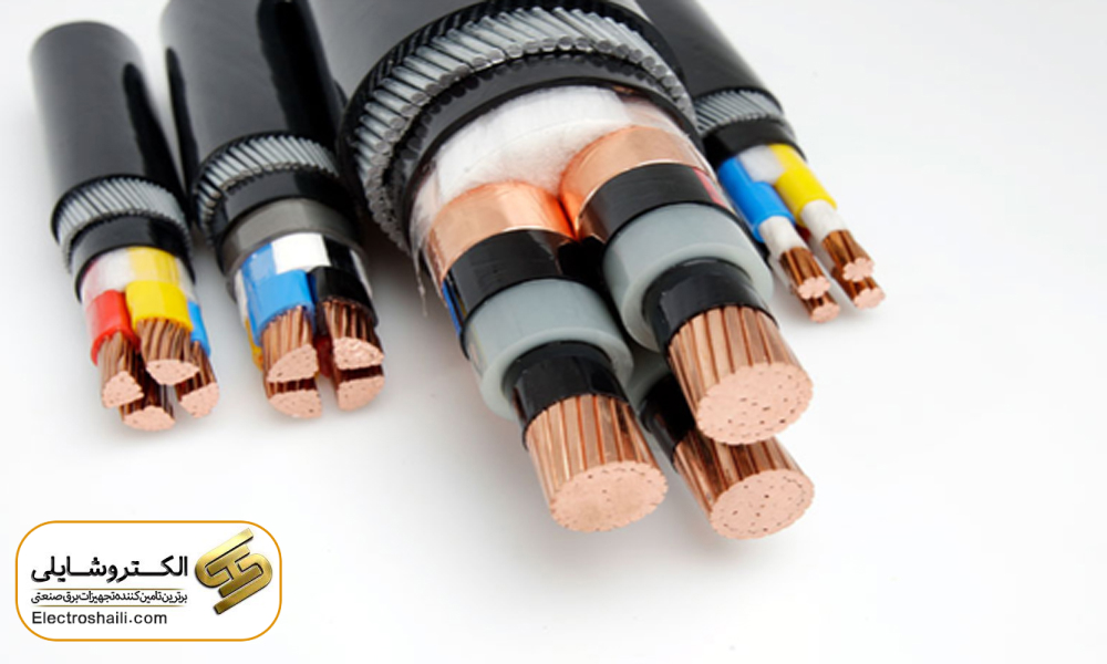
A conductor is a material that can conduct electric current well, known as a good conductor in the field of electricity. Conductors are usually made of materials such as copper, aluminum, or special alloys. The structure and dimensions of the cross-sectional area of conductors vary depending on the needs and applications.
In electrical installations in buildings, copper with 99.5% purity is commonly used as a conductor due to advantages such as low electrical resistance, excellent electrical conductivity, resistance to weather conditions, suitable mechanical strength, and malleability. Aluminum, with advantages such as good mechanical strength, malleability, lower electrical conductivity than copper, and economic benefits compared to copper, is also used. However, aluminum has disadvantages such as lack of resistance to weather conditions, which may lead to its oxidation, and a lower yield point.
Skin Effect on Conductors
The skin effect refers to the tendency of alternating current to distribute in regions close to the surface of the conductor. This current distribution is due to the frequency of alternating current at a depth from the surface to the skin. The skin effect increases the effective resistance of the conductor, ultimately affecting its electrical conductivity.
Summary
This article covers various topics in the field of electrical distribution systems. It starts by discussing the calculation of the cross-sectional area of the conductor based on the permissible voltage drop in consumer loads in low-pressure systems. It then explores voltage drop and cross-sectional areas of three-phase circuits, highlighting important points in this area.
Furthermore, it discusses the electrical resistance of wires and cables in alternating current, and the effects of the skin effect on the electrical conductivity of conductors are examined. Finally, it addresses issues related to closed distribution networks and variable cross-sections. This article, with an emphasis on technical and scientific aspects, provides useful information in the field of power distribution.