Examining Types of Building Electrical Panels
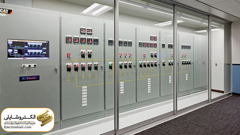
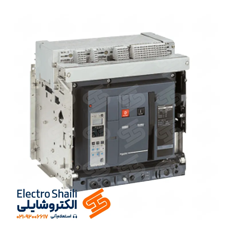
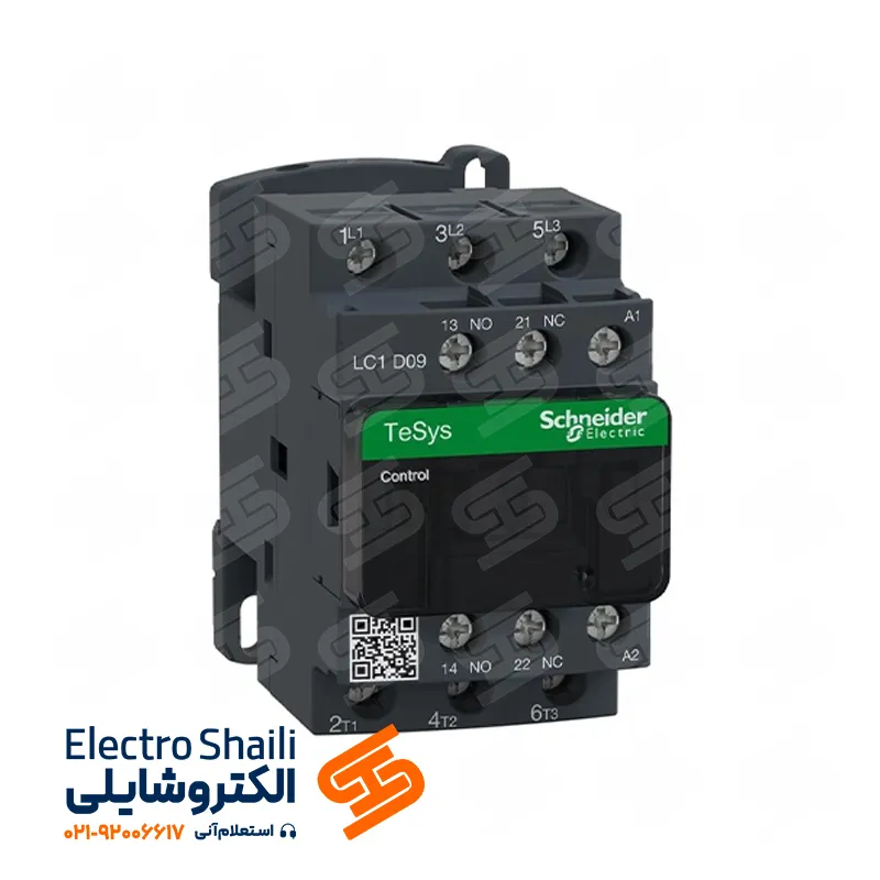
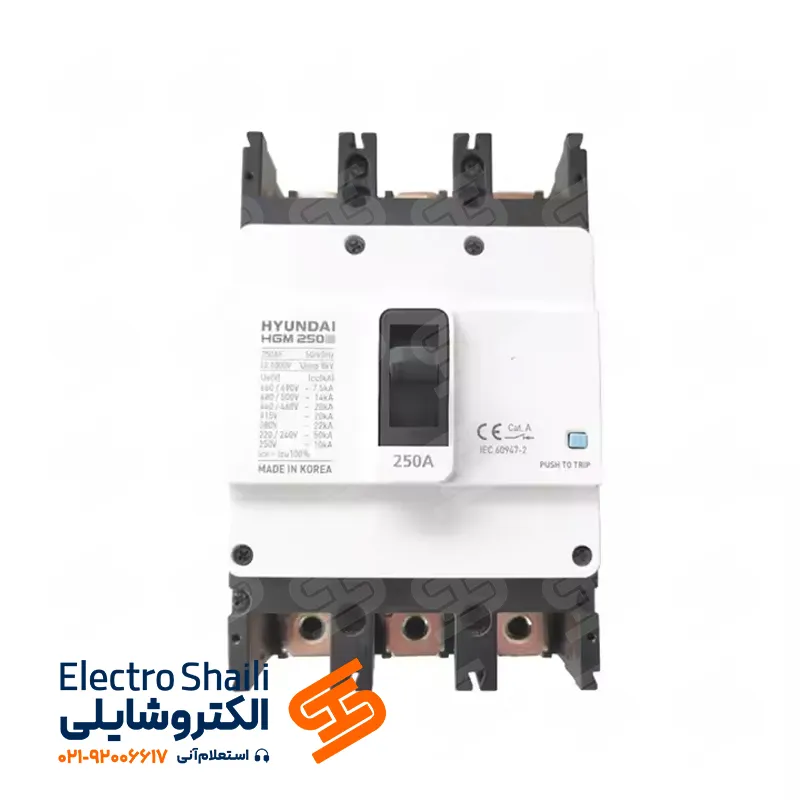
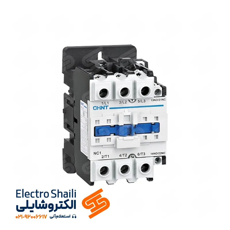
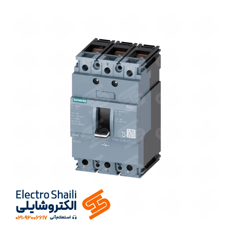
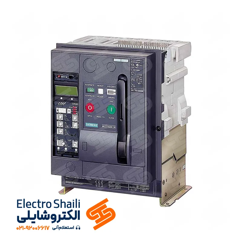
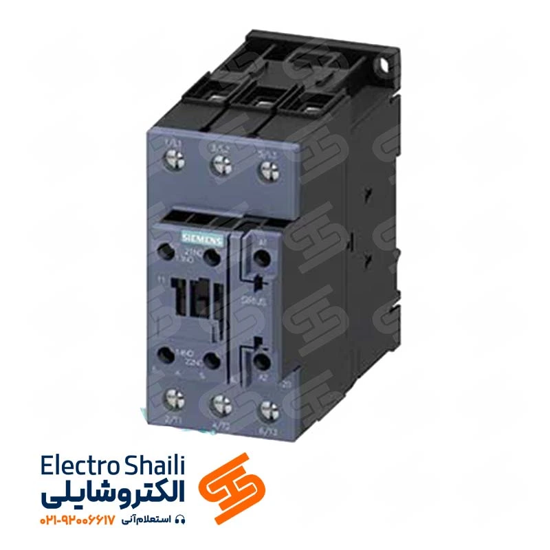
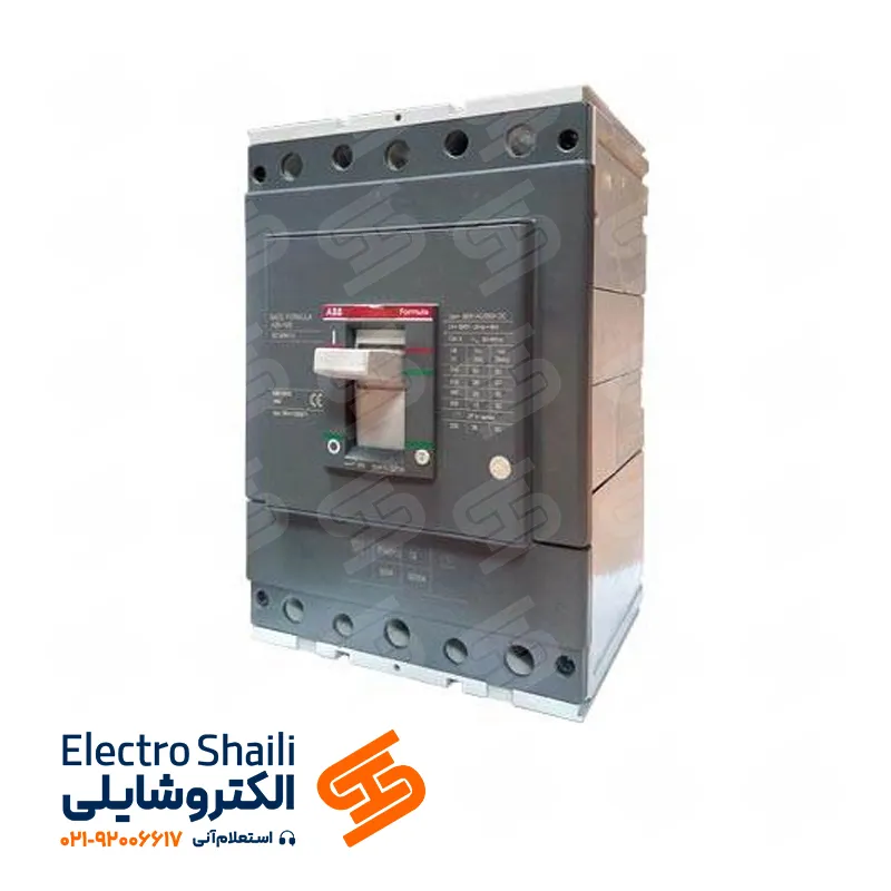
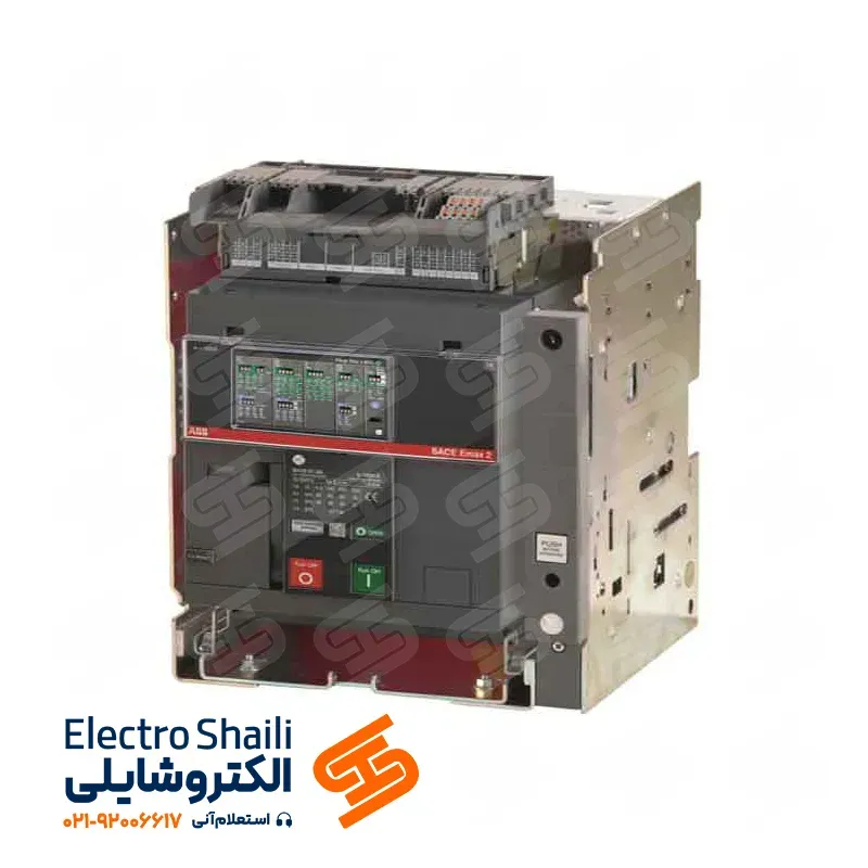
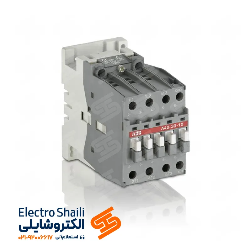
Electrical panels in the industrial and building sectors are divided into various categories. The main purpose of these panels is to protect circuits, control and command them, and manage power distribution in buildings and electrical equipment. The protective and control elements of these panels include automatic switches, magnetic switches, circuit breakers, control relays, and displays. These circuits prevent hazards such as short circuits, overloads, fires, and electric shocks, facilitating the easy startup and control of electrical equipment. Below, we will explore different types of building electrical panels.
Types of Building Electrical Panels
Next, let’s examine the types of building electrical panels.
Main Distribution Panel (MDP)
Common Area Panels GDB or GDP
Unit Panels Miniature Panel (SDP or SDB)
Low Voltage Panel
Elevator Panel (if needed)
Diesel Generator Power Distribution Panel (if needed)
UPS Power Distribution Panel (if needed)
Main Distribution Panel (MDP)
The main distribution panel or MDP is one of the main types of building electrical panels used to protect and control the main electrical circuits of the building. This panel, equipped with advanced protective and control components, ensures the best possible safety and efficiency of electrical power in the building.
After entering the building, the main power cable connects to the main electrical panel or counter panel (MPD). This panel is responsible for supplying power to all building units and common areas. The main electrical panel is one of the main types of building electrical panels and is divided into three main parts:
Power Entry Section (related to the power company):
Counter Section:
Service Section:
Power Entry Section (related to the power company):
The entry section of the main electrical panel consists of a 4-core cable with a cross-sectional area of 16 square millimeters. This cable includes three phase wires and one PEN wire. The three phases are connected to the input of the automatic switch, which is used to balance and supply power to the building’s main system.
The output of the automatic switch feeds two essential sections:
Glass Fuse Input:
This section is dedicated to protecting signal lights and digital three-phase meters.
Secondary Fuse Input:
The output of each glass fuse is connected to a signal light, and the other end of the signal light is connected to the neutral. Also, the outputs of the secondary fuses are placed on separate phase rails so that the input of each counter can be connected to these rails.
In the next step, branching is taken using the busbar. This busbar consists of a metal strip with multiple holes.
Input and output wires are twisted and secured with insulation sleeves to prevent contact with the busbar. This section of the panel is sealed by the electrical department, and the responsibility for maintenance and safety measures lies with the electrical department. The fourth wire acts as a protective-neutral and is first connected to the ground bar and then to the jumper neutral bar.
Counter Section:
The main distribution panel or counter panel plays a key role in power distribution in the building. This panel is located at the entrance point of the building and is responsible for supplying power to all units and common areas. This panel is usually labeled as MDP on electrical drawings. The main cable, often entering from the bottom, connects to the fuse key of this panel, which is of the disconnectable type.
After entering the building, the main cable joins this panel, and the number of counters is determined based on residential units and the presence of a shared panel. For example, a four-story building with a main panel containing five counters, one of which belongs to the common panel and the rest to the units. The unit counters are implemented as single-phase, and if there is an elevator in the building, the shared panel will be three-phase; otherwise, it will be single-phase.
In the middle of the panel, electrical circuits for distribution to the units are placed. Contactors are installed in this section to feed the output of each fuse key to the counter. When connecting the phases to the counters, balancing the load on the phases is essential, and labels are provided next to each input line to the counter. For this reason, in some panels, we use phase control relays.
The phase control relay plays a role in circuit protection against overvoltage, undervoltage, asymmetry, and phase sequence. This relay is installed at the beginning of the circuit, after the fuse. The neutral bar must be placed on insulators (insulation bases). One neutral bar is mandatory for each unit in the main electrical panel. In the absence of this requirement, a life-saving or RCD protector is used in the miniature panel of the unit.
In this case, wires and cables are connected to the neutral bar in a spiral manner, and the connection of the phase to the respective equipment is made. The phase bars, with sufficient strength and without insulation, connect the phase to the respective equipment while maintaining color-coding for the phases. The ground bar is directly mounted on the panel, and the installation location of the ground bar must be colorless. If the panel is colored, the part connecting the ground bar to the panel must be trimmed. Failure to trim the colored part may result in poor contact due to the insulating nature of the panel color. The metal body of the panels must be connected to the ground.
The outputs of the counters are connected to the miniature key of each unit. The outputs of the miniature keys of each unit are connected to the 30 mA life-saving protector of that unit. The 30 mA RCD output is connected to the RCT terminals and is connected to the power distribution panel of the floors from the terminal outputs. A three-phase key is used for the common area panel, and its output is connected to the common area panel.
After connecting the wires to the ground bar, they are formatted. For regular wiring inside the panel, ducts and in some special cases, plastic belt buckles are used. During wiring, cables and wires must be labeled.
Explanation of the Counter Panel (MDP) Diagram
The Counter Panel, known as MDP, is equipped with three-phase electricity with input cables of 3 * 10mm² and 1 * 6mm² in diameter. The main feeder selection for the panel is made in proportion to the building’s needs. Three phase wires enter the fuse switches, which should be of the type that can be easily disconnected under load, and are installed at the bottom of the panel, at the point where the main cable enters.
The three wires corresponding to the L1, L2, and L3 phases are connected to the lamp heads, and the other ends of the lamps are connected to each other. Each lamp is equipped with a glass fuse at its path. Due to the extensive use of neutral and ground wires, a separate channel (copper strip) or terminal is considered for each line. The cross-sectional area of the strip must be carefully calculated. Each output from the fuse switch must be connected to a separate strip so that the input of each contactor can be connected to these strips after being divided among the phases. The ground connection strip must also be connected to the metal body of the panel and its doors.
Important Points Regarding the Main Counter Panel:
– The design of the main counter panel is the responsibility of the power distribution company.
– The installation location of the counter panel should be optimized and near the entrance for allocating power branches. The final installation location is determined in coordination with the power distribution company and the project supervisor.
– In large commercial and residential complexes, the counter panel is not installed in the basement.
– A multi-stranded copper wire is introduced as a grounding well into the grounding strip of the counter panel, and its cross-sectional area must be calculated according to the standards and recommendations of the power company and specified on the diagrams.
Common Area Panel (GDB)
The Common Area Panel is a vital electrical equipment designed to supply power to a section of the building used collectively by all residents, such as stairwell lighting, parking areas, roof, and courtyard. The installation of the common panel should be in a position easily accessible.
This panel is mainly installed in the utility rooms and is indicated on the diagrams with “GP”. Additionally, central antenna systems, intercoms, fire alarm systems, engine rooms, and elevators are also powered by this panel. To build the panel, the required lines need to be estimated, and the diagrams of the common panel circuits are provided to the panel manufacturer. This estimate includes counting the number of circuits needed for lighting, water pumps, intercoms, and other common components.
The common panel has 13 lines, and after estimating the lines, the panel frame is installed on the wall. If the wall is a plasterboard wall, the frame is easily secured by plaster; otherwise, it should be stabilized using suitable supports. After installing the panel, piping is done for the lines under the frame, and then the pipes are cut or laid as needed. Then, the main wiring and cable laying steps are taken, and finally, the panel is connected.
For the input of the common panel, a miniature switch and a suitable three-phase breaker are selected based on the panel’s consumption. Three wires related to the three phases enter the three-phase miniature switch, and the output of this switch powers the panel. It also has one output for supplying a 2-ampere glass fuse for signaling lights. The second output is for supplying the fire pump, and the third output is used to power other common circuits. This panel is installed and executed with precision and adherence to safety standards to ensure optimal power supply to common areas of the building.
Explanation of the Main Electrical or Common Area Panel Diagram
The Main Electrical or Common Area Panel is a fundamental component in supplying power to common sections of the building and uses a 5 * 6mm² cable for input. A three-phase switch miniature and a breaker are selected for the input based on the panel’s consumption. The line voltage structure (phase-phase) provides 400 volts, and the phase voltage (phase-neutral) provides 230 volts.
After entering the panel, the main switch is connected to the 0-1 rotary switch to be able to turn the main power of the panel on and off with a switch. The phase wires enter the three-phase fuse, and the nominal current of the fuses is calculated based on the panel’s consumption. Three signal lamps are used to display the presence of the electrical panel.
This electrical panel is designed to supply power to shared uses among all units. For the lighting of stairwell services, parking, engine rooms, elevator shafts, courtyards, roofs, and other areas, multiple lines with 1.5mm² wires and 10-ampere fuses are considered. Additionally, for the outlets used in these areas, multiple lines with 2.5mm² wires and 16-ampere fuses are used. Each line is labeled with the phase name.
If there is an elevator or engine room for heating and cooling systems, a three-phase GP panel is used, and a three-phase output line with a three-phase fuse is considered for the elevator panel. The size of the output cable from the shared panel to the elevator panel is determined to be 5 * 6mm², and a three-phase 20 or 25-ampere miniature switch is used.
Outputs of Building Electrical Distribution Panel
In general, the outputs of distribution panels for building common areas are configured as follows:
1. If there is a common areas panel on the building roof, a single-phase output is required for the central antenna system amplifier. This output should have three wires with a minimum cross-sectional area of 1.5 square millimeters and a miniature switch with a 10-ampere class B rating.
2. For supplying the intercom in the main common areas panel, an output with three wires and a minimum cross-sectional area of 1.5 square millimeters, along with a miniature switch with a 6-ampere class B rating, is considered.
3. If a fire alarm control panel is present in the main common areas panel, a single-phase miniature switch with a nominal current of 10 amperes and class B, with three wires and a minimum cross-sectional area of 1.5 square millimeters, should be considered.
4. For lighting in the common areas of the building, usually, one or more outputs with a 10-ampere class B miniature switch and three wires with a cross-sectional area of 1.5 square millimeters are considered.
5. Considering the presence of multiple outlets in the common areas, several outputs in the main common areas panel with a 16-ampere class C miniature switch and three wires with a cross-sectional area of 2.5 square millimeters are provided.
6. If an exhaust fan is present, one or more outputs and a 10-ampere class B miniature switch are considered based on the needs in the distribution panel for common areas.
It should be noted that for water pressure booster pumps and firefighting pumps, a class C miniature switch is used, taking into account the motor power.
Installation of Equipment Inside the Common Areas Electrical Panel
To ensure neat wiring inside the common areas panel, ducts and, in some cases, plastic belt ties are used. During the wiring process, it is necessary to label the cables for identification.
The neutral bar is placed on insulating supports, and the ground bar is installed on the panel so that there is no color underneath it. If the panel is painted, the color where the ground bar connects to the panel must be removed.
Attention:
Many panel builders use wires with a cross-sectional area of 2.5 square millimeters for a 25-ampere miniature switch, which contradicts national building regulations. For this reason, inspectors must carefully consider the wire cross-sectional area and the amperage of miniature switches. Also, due to the three-phase nature of the panel, the load distribution should be symmetrical.
Securing the wires under the screws and terminals is crucial. If the connections are not secure, there is a possibility of circuit interruption or damage.
If a staircase timer is used for staircase lighting, the timer should be directly connected under itself.
If a three-phase pump is used in the building, it is installed in the control panel and connected to the pump using terminals under the contactor.
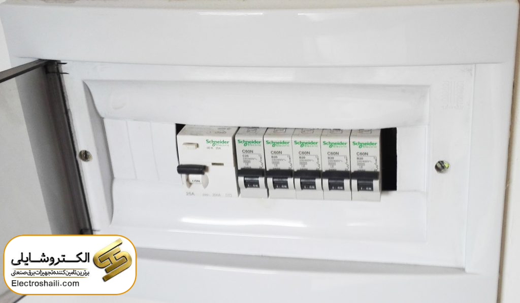
Unit Electrical Distribution Panels
These panels are used to provide power to lighting circuits and outlets in each residential unit. They replace scattered distribution boxes in older buildings and are used in the wiring system. In this method, wiring is completely separate for weak current systems, lighting power, and outlets, utilizing the distribution panel.
One advantage of this method is that in case of a connection or fault in a part of the building or even the kitchen, repairs and modifications are quickly done. The installation location of these panels can be seen in the building outlet plans with the symbol DP.
Explanation of the Unit Distribution Panel Diagram
This panel is called the DP Unit Distribution Panel and is used in electrical diagrams. This panel is powered by a 3*4 square millimeter cable with three NYY type wires with a cross-sectional area of 4 square millimeters. The choice of input cable is based on the consumed load, and this cable is made of PVC with two layers of plastic insulation in the NYY model.
After passing through the main miniature fuse, the phase wire enters the miniature switches corresponding to each line. Some of these panels have signal lamps to indicate the status of power connection or disconnection in the panel.
In the output lines of this panel, ground, neutral, and phase wires that have a miniature fuse in their path must be present. The type of line (such as lighting or outlet) must be specified on the panel.
According to regulations, the allowed current value for lighting circuits is 10 amperes, and for outlets, it is 16 amperes. For special purposes such as air conditioners, the wire cross-sectional area and the fuse amperage should be calculated and selected based on the device’s power.
Important Points for Unit Panel Design
In the design of unit distribution panels, the following important points should be carefully considered:
1. The suitable location for the unit panel in residential units should be near the entrance and utility ducts.
2. After the main miniature switch in the panel and on the load side, the installation of a Residual Current Device (RCD) with a 30-milliampere residual current is essential.
3. Pipes related to the input cable of the unit panel should pass through the electrical installation ducts of the building.
4. The number of panel lines must be coordinated with the number of lines designed in lighting and outlet plans.
5. The number of reserve lines must also be acceptable and reasonable.
6. The cross-sectional area of the input and output cables of the panel must be consistent with the riser diagrams of the panels and the information on lighting and outlet plans.
7. Separate grounding for the electrical panel must be considered.
8. The size of the unit panel cables should be in line with the requested load and demand, considering temperature correction factors, allowable voltage drop, allowable current, and coexistence of important factors.
Outputs of Power Distribution Panels in Residential Units:
The outputs of power distribution panels in residential units are extensive and include the following:
- Multiple outputs for lighting with three-core wires containing a minimum cross-sectional area of 1.5 square millimeters (NYAF 3*(1*1.5)mm²) and a 10-amp miniature switch, Class B, is considered.
- Multiple outputs for power sockets with three-core wires containing a minimum cross-sectional area of 2.5 square millimeters (NYAF 3*(1*2.5)mm²) and a 16-amp miniature switch, Class C, is considered.
- One or more outputs for gas coolers or split systems with a three-core cable containing a minimum cross-sectional area of 4 square millimeters (NYY 3*4mm²) and a 20-amp miniature switch, Class C, is considered. When selecting the miniature switch, attention to its Class B or C is mandatory.
- For audio systems, cameras, motorized curtains, jacuzzis, special lights, coil fans, and similar items, one or more outputs with the appropriate number of wire strands, suitable cross-sectional area, and suitable miniature switch are considered.
- A minimum of two reserved lines with currents of 10 and 16 amps for lighting circuits and sockets are considered.
- The electrical score provided by the power company to each residential unit is 25 amps at 220 volts. Therefore, the total installed power and maximum power demand for each panel are divided by 5 kilowatts with a power factor of 0.9.
Elevator Power Distribution Panel:
Power distribution for elevators is a vital part of building infrastructure. When designing and drawing a single-line diagram for the elevator power distribution panel, the following points are carefully considered:
- Precise drawing of elevator power distribution panel maps is essential as it is a vital part of the building’s electrical system.
- The elevator power distribution panel is directly connected to the main distribution panel of common areas. In the presence of a diesel generator in the building, the elevator supply cables are first connected to the ATS panel and then to the elevator power distribution panel.
- The electrical consumption of the elevator shaft is directly supplied from the main elevator panel.
- The installation location of the elevator power distribution panel must be inside the elevator machine room and in a way that does not interfere with the machine room door.
- The input of the elevator panel includes a miniature switch and a three-phase cable, determined based on the elevator panel’s consumption needs.
Outputs of Elevator Power Distribution Panel:
The outputs of the elevator power distribution panel are provided using various miniature switches:
- A single-phase 10-amp miniature switch with three-core wires and a cross-sectional area of 1.5 square millimeters is used for the illumination of the machine room.
- A single-phase 10-amp miniature switch with three-core wires and a cross-sectional area of 1.5 square millimeters is used for the illumination of the elevator shaft.
- A single-phase 16-amp miniature switch with three-core wires and a cross-sectional area of 2.5 square millimeters is used to supply power to the outlets in the machine room and shaft.
- A three-phase 20 or 25-amp miniature switch, dependent on the elevator motor current, with five wire strands and a cross-sectional area of 6 square millimeters is used to supply power to the elevator control panel.
Main Electrical Panel Services:
Currently, implementing the services section in the main electrical panel is not considered a mandatory step; hence, some panels may not include this section. In this section, the possibility of installing items such as intercom transformers and telephone lines arises.
In some cases, common area miniature switches are also installed in this section and serve as common area panels. In such cases, it is essential to ensure that low-voltage electricity does not create noise on the low-current section (telephone and intercom). If the wiring volume in the common areas is significant, it is recommended to install a separate panel for common areas.
The number of telephone lines is determined by the property owner and is then communicated to the telecommunications provider. The telecommunications terminal (telephone jack) is connected to the panel body using screws. The main telecommunications cable is connected to the input of this terminal, and the unit cables are connected to its output in sequence from bottom to top, respecting the color-coding of the pairs. In the market, there are two different types of telecommunications terminals.
Key Factors in Selecting Building Electrical Panels:
- Design Type Consideration: Carefully examine the design of the electrical panel based on the specific needs of the building. This includes the type and variety of internal and external components, displays, and control keys.
- Compliance with Design Standards: Ensure that the electrical panel complies with relevant design and safety standards. This is crucial for both performance and safety.
- Panel Size Selection: Choosing the appropriate size based on the electrical needs of the building is crucial. This includes the number and type of electrical equipment in the building.
- Thickness of Used Sheets: Make sure that the sheets used in the electrical panel are of high-quality material with an appropriate thickness to guarantee the safety and lifespan of the panel.
- Intended Use Location: Determine whether the electrical panel will be installed indoors or outdoors and consider its resistance to the relevant environmental conditions.
- Entrance and Exit Points for Wires and Cables: Clearly specify where the wires and cables enter and exit to facilitate installation and maintenance.
- Quality Level: Ensure that the electrical panel is made from quality materials and utilizes advanced technologies to provide a longer lifespan and better performance.
- Intended Application: Consider specific application needs such as control features, automated systems, and other functionalities, and choose the electrical panel accordingly.
- Presence or Absence of Protective Systems: Decide whether the electrical panel requires a protective system or not, and if yes, specify the desired type of protection.
- Electrical Panel Price: Consider an exact budget amount for purchasing the electrical panel and evaluate the alignment of quality and provided features.
Conclusion:
This article covered topics related to power distribution panels in residential and commercial environments. It first discussed the various outputs of power distribution panels in buildings, including lighting, sockets, intercoms, and various systems. Then, it delved into design considerations for these panels, such as appropriate placement, miniature switches, and correct internal and external connections.
Additionally, explanations related to the equipment inside the panels, installation and startup of various equipment, and power supply for different building components were provided. Finally, insights into the diagrams and circuits of the panels, as well as main electrical panel services, were discussed.

