Everything You Need to Know About Grounding or Earthing Systems
Soil, composed mainly of substances with electrical conductivity, especially in humid conditions, plays a crucial role in grounding systems. When someone comes into contact with a body that has an electric potential with respect to the ground, there is a risk of electrical shock due to the electric current generated. Ground is utilized as a path for the return of electric current since the current flows through it. Therefore, the use of a grounding system is essential.
Many hazards for individuals and electrical equipment arise from the absence or weak grounding connection. A low-resistance grounding system has the least incidents for workers. In a system without grounding, where the phase voltages are balanced, intentional or accidental contact with any of the phases can lead to a serious electric shock.
When a ground connection (earth bond) is not made on one of the phases of the grounding system, the person who comes into contact with one of the other phases and the ground may be under a voltage 73 times the grounded system voltage.
The lack of an appropriate grounding system poses risks such as fire and serious damage to equipment and installations. Therefore, having a proper grounding system is one of the ways to prevent life-threatening incidents and equipment damage.
Ground as an Electrical Conductor
Ground, one of the vital components in electrical systems, is often made of materials that predominantly conduct electricity, especially in moist conditions. This property causes the ground to act as a path for the return of electric current when a person comes into contact with the ground, which has an electric potential relative to the body.
The Earth’s crust can be considered as a reference with a constant potential, i.e., zero potential. This zero potential is applied to all parts connected to the ground through conductors, and in reality, electrical equipment is directly connected to this zero potential. In the event of a short circuit in the conductor, the area around the ground connection (grounding system) approaches a similar voltage, preventing the dangerous touch voltage.
Ground is, in fact, a conductor of electricity, and its resistance depends on the type of soil composition. For example, in areas with dry sand and gravel, the resistance of the ground is much higher, while moist and clayey soil has lower resistance.
In the context of electrical systems, if the system load is balanced, no current will pass through the ground. However, if the current in one of the phases is greater than the other two phases, the vector sum of the currents at the neutral point will not be zero, and the current will flow through the neutral wire. The details of calculations for the current flowing through the neutral wire and the effects resulting from the system’s imbalance have been examined and calculated.
Optimizing Earthing or Grounding: Concept and Applications
Earthing or grounding is a crucial action in the electrical field, involving the creation of an artificial electrical connection to the ground with very low resistance to prevent the flow of electric current. In electrical terminology, the term “ground” refers to a point with zero potential. When a point in the network is connected to the ground, that point serves as the ground, and if multiple points in the network are grounded, they are recognized as multiple grounds.
Grounding or earthing a electrical system means connecting all metallic components or metal bodies of electrical devices to the ground. The primary goal of this action is to transfer any type of electrical energy leakage in the metallic body of the device to the ground to protect individuals and equipment.
Protection through grounding wire is a type of electrical protection that connects non-conductive parts of the device to the ground. As long as no connection is made in the device body, the protected parts of the device will always be at ground potential.
If the electrical components of the device are connected to its body, a current from the body to the transformer’s zero point will flow through the wire to the ground. The amount of this current must be sufficient to quickly cut off the fuse in the event of a fault current and disconnect the touch voltage. The amount of the cutting current depends on the resistance of the grounding wire and the resistance of the wire contact points with the ground.
Using this protective system is suitable for low-power consumers because, in the case of high consumer currents, the ground resistance must be very low, which is challenging. To achieve the proper ground resistance, suitable resistance can be obtained by placing strips and pipes or specific thickness and length plates in the soil and connecting the bodies of systems that need protection to it.
Explanation of Basic Concepts in Electrical Connections
1- Ground
The concept of ground refers to a conductive mass considered as a reference with zero potential at all points in the environment.
2- Ground Electrode
The ground electrode is a conductive body placed in the ground and connected to the ground wire. These electrodes, to establish an electrical connection with the conductive mass of the ground, are placed underground.
3- Ground Connection Conductor
A part of the grounding system that connects the ground electrode to the main grounding terminal or busbar is called the ground connection conductor.
4- External Conductor
Conductors that are not connected to electrical equipment but have the potential to create a potential like ground potential are called external conductors. This includes the metal skeleton of the building, metal pipes for water, gas, and other elements.
5- Protective Conductor or PE Wire
A conductor connected to various parts in protective actions, including the grounded point of the power distribution system or artificial neutral (ground), ground terminal, accessible conductors, and external conductors.
6- Protective PEN Neutral
A neutral wire that is grounded and performs the function of both the neutral wire and the protective conductor.
7- Independent Ground Electrodes
Independent ground electrodes refer to ground electrodes where the current flow through one of them has little effect on the potential of the other electrodes.
8- Fault Current
Current resulting from insulation breakdown or short-circuit.
9- Ground Fault Current
Current that flows through the ground.
Diversity in Grounding Systems
Here, we examine various types of grounding systems:
1. Safety Grounding System:
This type of grounding is carried out to stabilize the neutral point of transformers and generators and avoid electrical hazards in equipment.
2. System Protection Grounding:
This system connects the metal body of electrical equipment that is not in direct electrical contact with the circuit to the ground to prevent electric shock.
3. Operational Grounding System:
This system connects electronic devices in low-current systems such as computer centers, data centers, telephone centers, telecommunications, and communications systems to the ground. The goal is to ensure the proper and safe operation of equipment.
4. Lightning Protection Grounding System:
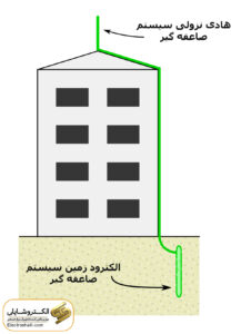
This system refers to the grounding of the down conductor of the lightning protection system to the ground in high-rise buildings. Grounding electrodes for protection, operational, and lightning protection systems should be connected to each other and connected to the main grounding terminal or busbar.
In the convergence of these elements, ensure that connections are properly made, and the system operates fully.
Diversity in Electrical Connections and Current Faults
In the world of electricity, different connections can lead to faults caused by electric current:
1. Body Connection:
This connection occurs when one of the electric current wires (phase) is connected to the body of the device. This fault may lead to energy loss and voltage drop.
2. Short Circuit:
This type of connection occurs when two conductors with different electric potential are connected to each other. This situation can cause heat generation and serious hazards.
3. Ground Fault:
This connection occurs when one of the current-carrying wires (phase) is connected to the ground. Grounding can improve system safety, but if done incorrectly, it may pose hazards.
While complete connections should be without resistance for the current to pass effectively, incomplete connections can lead to voltage drop and other problems. Checking and correcting connections correctly are of special importance.
Advantages of Grounding in Electrical Systems
1. Improved Performance of Surge Protectors:
Grounding improves the performance of surge protection devices and prevents damages resulting from voltage surges.
2. Increased Speed in Detecting Connections and Faults:
Grounding provides sufficient speed for identifying incomplete connections and faults in the system. Relays help in promptly resolving faults.
3. Voltage System Control:
Grounding prevents voltage rise due to incomplete connections and voltage drop due to load imbalance.
4. Protection of Personnel Lives:
One of the main advantages of grounding is the protection of individuals engaged in the electrical system from electric shock hazards, from operators to maintenance personnel.
5. Protection of Electrical Devices:
Grounding acts as a protective shield and safeguards electrical devices from hazards arising from voltage drops or incomplete connections.
Types of Grounding in Electrical Installations
1. Protective Grounding:
Protective grounding involves connecting all metal components in electrical installations that do not have a direct electrical circuit to the ground. This type of grounding is especially used for protecting individuals against touch voltage.
The presence of a live wire on the metallic body of an electrical device creates a potential difference between the device body and the ground. If a person touches the device body, touch voltage occurs. If this voltage exceeds 50 volts, it is considered dangerous.
For example, if a supporting metal rod on a moist wall breaks, and the strong pressure grounding connection to the wall is established, ground fault current of 25 amperes with a resistance of 10 ohms per meter of the wall is created. In this case, the potential difference between two points on the wall that a person touches is calculated.
2. Use of Life Protectors:
One way to prevent electric shock hazards due to contact with the body of electrical devices is to use life protectors. These leakage current protectors detect leakage currents and, if necessary, disconnect the circuit.
Principles of Protective Grounding in Electrical Installations
Ground is made of materials that mainly conduct electricity, especially when moist. Therefore, contact with an object that has an electrical potential relative to the ground can lead to electric shock.
In the early history of the electrical industry, the neutral point of alternators and transformers was not connected to the ground. For small networks with short lengths and low voltage, grounding the neutral was not felt necessary. These networks were known as “separate neutral networks” or “not connected to the ground” or “ungrounded” networks.
These networks had advantages over grounded networks. For example, accidental connection of a phase to the ground did not result in significant current flow, and it did not cause power outages or disturbances. Also, in case of contact with a person’s body with one of the phases, due to the absence of dangerous current flow, electric shock did not occur.
With the development of networks and the increase in voltage, currents became noticeable in the event of a phase connection to the ground and were intermittently interrupted. This led to an increase in the voltage of healthy phases relative to the ground and damage to the network.
Connecting the neutral of the network to the ground prevents hazardous voltage build-ups on the metal body of electrical tools and equipment. The purpose of protective grounding is to prevent the establishment of high and hazardous voltages on the metallic body of electrical tools and equipment relative to the ground.
In this regard, creating a low-impedance path for effective current flow during ground connection is important so that fuses or protective relays can effectively act against excessive loads and various hazards.
Grounding Safety
Grounding safety is a critical aspect of electrical devices, involving the connection of a crucial point in the electrical device to the ground. For instance, grounding the star center in transformer or generator windings is of special importance, aiming to ensure proper device functionality and prevent electrical pressure increase in healthy phases when one of the phases contacts the ground. In other words, grounding the neutral wire in the network and the star center in three-phase transformers, as well as the K terminals of secondary C.T and P.T (current and voltage transformers), are examples of safety grounding practices. These methods are widely used to create an effective path for current discharge and prevent electrical hazards.
Ground Connection Resistance
The significance of ground connection resistance in electrical installations is vital. Many electrical installations are grounded or connected to the ground due to safety concerns. Additionally, some direct current (DC) power transmission lines with high voltage use the ground as a return conductor to carry approximate currents of several amperes. The specific resistance of soil depends on its composition, such as clay, sand, granite, and the degree of moisture, ranging from 5 ohm-meters to 5000 ohm-meters. For example, in spring, the specific resistance of moist soil may be around 50 ohm-meters, while in summer, when the soil becomes dry, it may increase to 300 ohm-meters. Moreover, soil resistance is influenced by temperature, increasing slowly as it approaches freezing and rapidly as the temperature rises. This emphasizes the direct impact of temperature on soil resistance and the importance of controlling and monitoring its condition in electrical installations.
Measuring Ground Resistance
To ensure the continuous efficiency of ground connection resistance, it is necessary to measure this resistance periodically.
The use of a measurement device called “megger” is essential for measuring ground connection resistance. This device has four terminals: two for measuring current and two for measuring voltage. This process ensures that the ground connection system functions correctly, and its resistance remains within acceptable limits. Regular measurement contributes to maintaining optimal performance of your electrical installations and prevents potential issues.
Resistance Between Two Ground Electrodes
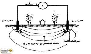
Despite the specific resistance of the grounding, the ground is an excellent conductor due to the large cross-sectional area it provides for current flow. For instance, if voltage (E) is applied between two electrodes in the ground, it is observed that the current flows throughout the volume of the ground, creating a path as shown in the figure below.
Even if two electrodes are several kilometers apart, the resistance between them remains relatively low. In the above circuit, four distinguishable resistances include:
1. Resistance of metal electrodes: Negligible
2. Connection resistance between electrodes and soil: Negligible
3. Soil resistance around each electrode: Important (depending on soil nature and electrode depth)
4. Ground resistance between electrodes: Negligible
Specific Ground Resistance
Specific ground resistance refers to the resistance measured in one cubic meter of ground between two plate electrodes with dimensions of 1×1 meter placed vertically. This resistance depends on the materials constituting the ground.
The resistance between the electrode and the ground depends on the specific resistance of the ground, which, in turn, varies depending on the type and moisture of the ground. Surface soils, due to their lower moisture content, have higher specific resistance.
To reduce electrode resistance in these cases, taller electrodes or the addition of conductive salts around the electrode are used to decrease the specific resistance of the ground. These measures improve the performance of the ground system.
Types of Ground Electrodes
1. Plate Electrode
2. Vertical Electrode
3. Horizontal Electrode
Plate Electrodes
Plate electrodes are most commonly used in humid and marshy areas, where plate electrodes with shallow depths are employed.
In this case, a plate electrode with dimensions of 0.5 x 0.5 meters is placed vertically in a pit, covered with approximately 20 centimeters of bentonite above and below the electrode, and then covered with a minimum of 1.5 meters of soil.
Using a plate electrode as the main electrode (for both types of ground, including system protection and safety) requires creating a well and an inspection hatch with dimensions of at least 30 x 30 x 30 in case of uncertainty about the presence of moisture and mud in the coming years. Additionally, for injecting water into the ground electrode, a PVC pipe with wide holes filled with gravel is used.
The height of this pipe from the surface level of the ground to the upper edge of the bentonite is 10 centimeters. Connecting the plate electrode to the copper conductor has two methods: one using main and lockable copper screws and nuts, and the other using exothermic welding. One common issue with plate electrodes is the loss of their connections.
Vertical Electrodes
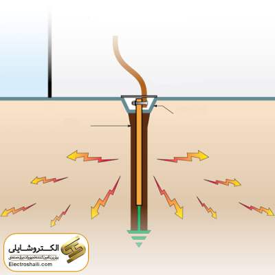
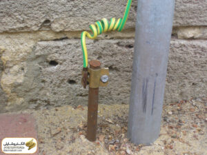
Vertical electrodes are among the most common types of electrodes due to their need for less space and more effectiveness. These electrodes include rod, pipe, and multi-strand wire electrodes. The minimum burial depth of vertical electrodes working in the ground is 2 meters.
The typical length of vertical electrodes is about 1.2 to 1.5 meters and can be extended. In other words, using a similar drill, the length of the electrode can be significantly increased and inserted into the ground. The ground electrode is usually installed near the meter board.
Horizontal Electrodes
The use of horizontal electrodes is mainly common in areas with sufficient space, and these electrodes are installed at depths of 0.5 to 0.8 meters from the ground surface in various forms.
System of Grounding Connection (Earthing) Implementation:
1. Initially, dig a hole with a depth of 2 meters and a width of 80 centimeters to reach moist soil.
2. Mix 150 liters of water with 50 kilograms of bentonite soil and pour the mixture into the excavated hole. This combination is chosen for its high moisture absorption, preventing it from solidifying for a certain period.
3. Place the copper plate connected to the grounding wire vertically in the center of the hole on the bentonite layer. The best method to connect the grounding wire to the copper plate is by using exothermic welding.
4. Use the bentonite and water mixture twice on the copper plate. For a hole with a diameter of 80 centimeters and a copper plate with an area of 50×50 centimeters, approximately 300 to 350 kilograms of bentonite and three times that amount of water are used.
5. To maintain the moisture in the hole, use a polyethylene pipe with a height of 20 centimeters installed inside the hole from the ground surface. This pipe allows injecting water drop by drop to keep the hole consistently moist.
6. After the bentonite has dried, fill the remaining hole with sifted soil and compact it.
7. After implementing the grounding connection, inspection covers are installed at the top of each grounding hole.
Key Points for Grounding in Distribution Systems:
1. One of the two secondary wires of a single-phase transformer with two wires.
2. The neutral wire of a single-phase three-wire system with low voltage.
3. The neutral wire of a four-wire three-phase system with low voltage.
4. The star point of a three-phase transformer.
5. Ground terminal of any switchgear.
6. The body or casing of all electrical devices, both air and ground transformers.
7. One secondary wire from each current and voltage transformer.
8. The neutral wire related to all subscribers at their entry point for electrical meters.
Main Bonding for Voltage Equilibrium:
Creating effective connections between all metal components of a structure to achieve voltage equilibrium and establish a common voltage surface is a fundamental principle in electrical safety. These connections include electrical connections such as grounding, neutral, metal water pipes, gas pipes, facility risers, cooling and heating systems, sewage, and other components.
Even metal air ducts must be connected to electrical equipment. This main bonding is achieved by connecting all metal components to each other and connecting them to the grounding system.
To ensure the creation of a permanent and reliable electrical path to the ground, a bonding jumper is used. This bonding jumper, made of metal materials, is connected to the metal pipes by a screw or clamp to establish a permanent connection path to the metal pipes.
Additional Bonding for Voltage Equilibrium:
The use of additional bonding for voltage equilibrium is necessary when there is a need for complete assurance of uninterrupted operation of devices such as fuses, miniature circuit breakers, and other automatic switches. In this case, additional bonding serves as an extra measure to maintain voltage balance for devices and equipment in use.
In additional bonding, all conductive or metal parts that are simultaneously accessible, including the metal body of electrical and non-electrical devices, foreign conduits, and grounds, are interconnected. This additional measure improves the reliability of flawless operation and prevents any accidental decoration in the performance of these components.
The use of additional bonding is especially necessary in humid environments such as swimming pools, saunas, and bathrooms to prevent any potential hazards associated with voltage and electrical components.
Reasons for Grounding Low Voltage Networks and Secondary Transformer Circuits:
Grounding the secondary circuit or low-voltage transformer has essential reasons that demonstrate protection against extra voltages and reactions arising from external factors. For example, the primary wire (high voltage) may be cut on the low-voltage network, or the insulation inside the transformer may break, connecting the primary winding (high voltage) to the secondary winding (low voltage).
By grounding the secondary (low voltage), the risk of shock is greatly reduced when touching the low-voltage network or transformer components such as radiators with the ground. Additionally, damages to the elements of the low-voltage system are reduced. By grounding the secondary (low voltage), in case of insulation failure of the transformer with other high-voltage sections, the primary fuses (high voltage) blow, isolating the faulty part of the circuit from the power source.
Also, transformer installations are designed in a way that if their body is touched by grounded individuals, the risk of electric shock is minimized. Therefore, it is necessary to ground the secondaries of transformers and measurement transformers to protect people’s lives.
Creating a Grounding System Using Deep Grounding Method:
Stage 1: Digging the Grounding Hole Initially, the grounding hole should be dug in a location with the lowest level, easily accessible to moisture in shallow depths. It is advisable to use locations such as grassy areas, gardens, or green spaces for digging the grounding hole. The depth of the grounding hole continues until reaching moist soil, with a minimum depth of 4 meters and a maximum of 8 meters, and a diameter of approximately 80 centimeters.
Stage 2: Connecting the Wire to the Copper Plate with Welding After digging the grounding hole, the wire is connected to the copper plate. In this stage, using brass or silver welding is recommended for the connection to be made in the best way.
Stage 3: Filling the Grounding Hole The last stage is filling the grounding hole. For this, a solution of water and salt is prepared and poured into the bottom of the hole to completely cover the bottom surface. Then, to a height of 20 centimeters, the bottom of the hole is filled with soil resistance-reducing materials.
Stage 4: Installing the Copper Plate The copper plate is installed vertically in the center of the hole. The area around the copper plate is filled with resistance-reducing materials up to its upper edge.
Stage 5: Installing the Polyethylene Pipe The perforated polyethylene pipe is placed on the top of the copper plate. This pipe is used for dripping water and preventing the hole from drying out.
Stage 6: Filling the Remaining Space of the Hole Finally, the remaining space of the hole is filled with clayey soil, sifted soil, or a mixture with sand. These stages of implementing the grounding system using the deep grounding method lead to the creation of an efficient and safe structural grounding.
Summary:
This article discussed the importance of grounding in low-voltage networks and transformers. The discussion included reasons why grounding the secondary circuit of the transformer is necessary and how this action can prevent serious incidents such as electric shocks and damages to system components. Additionally, the article touched upon the importance of primary and additional bonding in various construction areas and provided insights into the execution of grounding systems comprehensively and effectively.

