Shin or Busbar: Definition, Application, and Differences with Wire and Cable
In the world of electronics, you may have come across the terms “shin” or “busbar,” but you might not have precise information about their applications and significance. This article delves into the comprehensive details of the shin and helps you understand its concept, various types, and applications in electronic projects.
What is a Shin?
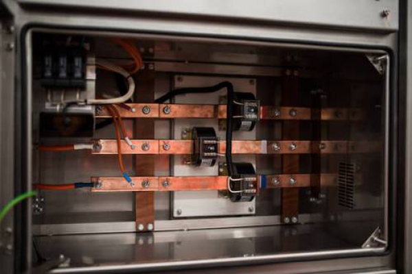
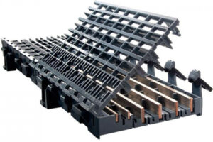
A shin is a vital component in electrical systems used instead of cables and wires for power transmission in electrical panels. These components are primarily made of copper or aluminum and have a rectangular or cuboid shape. The current-carrying capacity supported by shins should exceed the rated current of the equipment’s power supply. In simple terms, shins are responsible for collecting and distributing energy in an electrical panel.
When there is a need for transmitting a significantly high current in a power system, shins are used. Different types of shins are classified based on their standard current, and there are also subsidiary shins with lower amperage. To prevent potential hazards like electric shocks, these shins are covered with insulating material.
Advantages of Using Shin or Busbar in Electrical Panels:
The use of shins in electrical panels comes with various technical and safety advantages. When the electrical current increases significantly, the use of power cables will be limited. In such conditions, choosing shins as a powerful and safe alternative is possible. Shins offer better safety and performance compared to cables, especially in situations where high voltages are involved. For lower voltages, cables and wires are used as alternatives.
Other advantages of using shins include:
- Ease of replacing and substituting shins.
- Adding aesthetics to the electrical panel through the cuboid shape of the shin.
- High strength and power compared to wires and cables.
- Easy flow of electric current due to the unique cuboid shape of the shin.
- Creating branching possibilities in the system.
Basic Principles in Shin Configuration:
The configuration of shin arrangements is a broad and diverse field that requires careful attention to various details and criteria. Choosing the most suitable shin configuration, considering its pros and cons, is crucial. The basic principles in shin configuration include:
- Position of the Post in the Power System:
- Examining the precise position of the post in the power system and its role in supplying energy to consumers.
- Reliability:
- Providing the necessary reliability to ensure a stable energy supply to consumers.
- Feeder Voltage Levels:
- Evaluating the voltage levels of input and output feeders in shin configuration.
- Energy Transfer Capacity:
- Upgrading the energy transfer capacity in posts to optimize system performance.
- Number and Connection of Feeders:
- Determining the number and connection of feeding feeders and how they relate to the respective posts.
- Limitations:
- Identifying and examining existing limitations in the shin configuration.
- Cost Analysis:
- Analyzing the costs of posts and other economic factors influencing decision-making.
- Flexibility:
- Enhancing the flexibility of the shin configuration to adapt to system changes and variable needs.
These principles, in collaboration and consideration of the specific requirements of each project, serve as an effective guide in structuring an optimal shin configuration.
Analysis of Types of Bends in Busbars
What is the concept of bending in busbars? To maximize the efficiency of busbars in electrical panels, it is necessary to bend their shapes. These bends can be done manually or with machinery and come in various types, which we will introduce below.
Bending in Thickness:
This type of bend is used to establish better connections between adjacent busbar components. The size of the bend in thickness is determined by the distance between two terminals that need to be connected. This bend is done in circular and elliptical forms and requires heating the busbar to achieve the bend properly.
Bending in Width:
Bending in width is used to change the direction of the busbar’s path, and the angle of this bend is usually 90 degrees. This type of bend has the ability to create arbitrary angles.
Rotary Bend:
In this type of bend, the busbar is twisted and turned, used when there is a need to change the direction of the busbar’s surface. This directional change should occur along the axis and parallel to the busbar’s movement.
Step Bend:
This bend is used when two pieces are not parallel, and its purpose is to create electrical connections between two non-parallel pieces.
Busbars are recognized as crucial components in electrical equipment and come in various types that require careful understanding. Let’s continue to explore the types of busbars and their applications.
Phase Busbar:
Phase busbar is a type of busbar, and its electrical capacity should not be less than 150% of the rated current of the main switch supplying power to the panel. This type of busbar is used for distributing phase currents in electrical systems.
Ground and Neutral Busbar:
The ground and neutral busbar is used to connect grounding conductors, installing terminals for grounding operations and bonding. This type of busbar is vital in electrical safety and protection systems.
Tubular Busbar:
Tubular busbar is used for nominal currents exceeding 3000 amperes. This type of busbar utilizes specially designed tubes and efficiently conducts large currents.
Rectangular Cross-Section Busbar:
The rectangular cross-section busbar, usually made of copper, is used for internal installations. This type of busbar, with its rectangular dimensions, is recognized for its aesthetic and practical shape in electrical equipment.
Current-Carrying Busbar:
Current-carrying busbar or bus duct is used to connect phases and is typically used in large generators. This type of busbar is crucial for efficiently conducting large currents in power generation stations.
Busbar Coloring: Standards and Applications Guide
Coloring busbars is a fundamental standard in the electrical industry and plays a significant role in phase and neutral identification. Applying thermal colors to busbars facilitates quicker and more accurate phase and neutral detection. Additionally, busbar coloring, especially with specific colors, contributes to increasing the current-carrying capacity of busbars.
Other advantages of busbar coloring include ease of repairs, fault resolution, and providing services to the busbar. Commonly used colors for busbars include yellow, red, blue, and specific colors for ground and neutral busbars.
Busbars or Shin in Electrical Panels: Key Advancements and Applications
Busbars or shins in electrical panels fall into two main categories:
Main Busbars:
Main busbars are installed at the top of the panel or behind it, and their installation location is commonly known as the busbar chamber. These busbars play a primary role in transmitting current from the main source to other sections of the electrical panel.
Subsidiary Busbars:
Subsidiary busbars are derived from main busbars and are used to connect switches and other components of the electrical panel. The positional location of busbars in the electrical panel is of great importance, and the type of electrical panel is determined based on this location.
In summary, choosing and using busbar coloring contributes to increased efficiency and safety of electrical systems.
Complete Guide to Busbar Installation: Vital Tips for Success
Busbar installation requires adherence to vital tips to ensure better performance. Here, we examine these fundamental tips:
Selection of Busbar Cross-Sectional Shape:
Choosing the cross-sectional shape of the busbar depends on thermal resistance and the effects of the main current. This selection enhances the load-carrying capacity and torsional strength of the busbar.
Calculation of Busbar Conductor Area:
Calculating this area based on the maximum required current and the allowable current of the wires establishes electrical connections between the required equipment.
Maximum Continuous Temperature of the Busbar:
The type of busbar and its temperature are determined based on specific characteristics. The continuous temperature must consider various effects on the mechanical strength of the busbar according to its type.
Selection of Appropriate Color:
Using thermal colors on busbars not only facilitates phase and neutral detection but also provides advantages such as ease of repairs and service. Standard colors such as yellow, red, and blue are common.
In conclusion, busbars are highly important industrial electrical equipment. These conductive components play a vital role in establishing electrical connections between various pieces of equipment. Optimal performance of busbars can be achieved by choosing the right shape and cross-section.

